Backlight device and liquid crystal display apparatus
A backlight device and light source technology, applied in the direction of lighting devices, lighting device components, optics, etc., to achieve good image quality, expand the color reproduction range, and suppress the increase in power consumption
- Summary
- Abstract
- Description
- Claims
- Application Information
AI Technical Summary
Problems solved by technology
Method used
Image

Examples
Embodiment approach 1
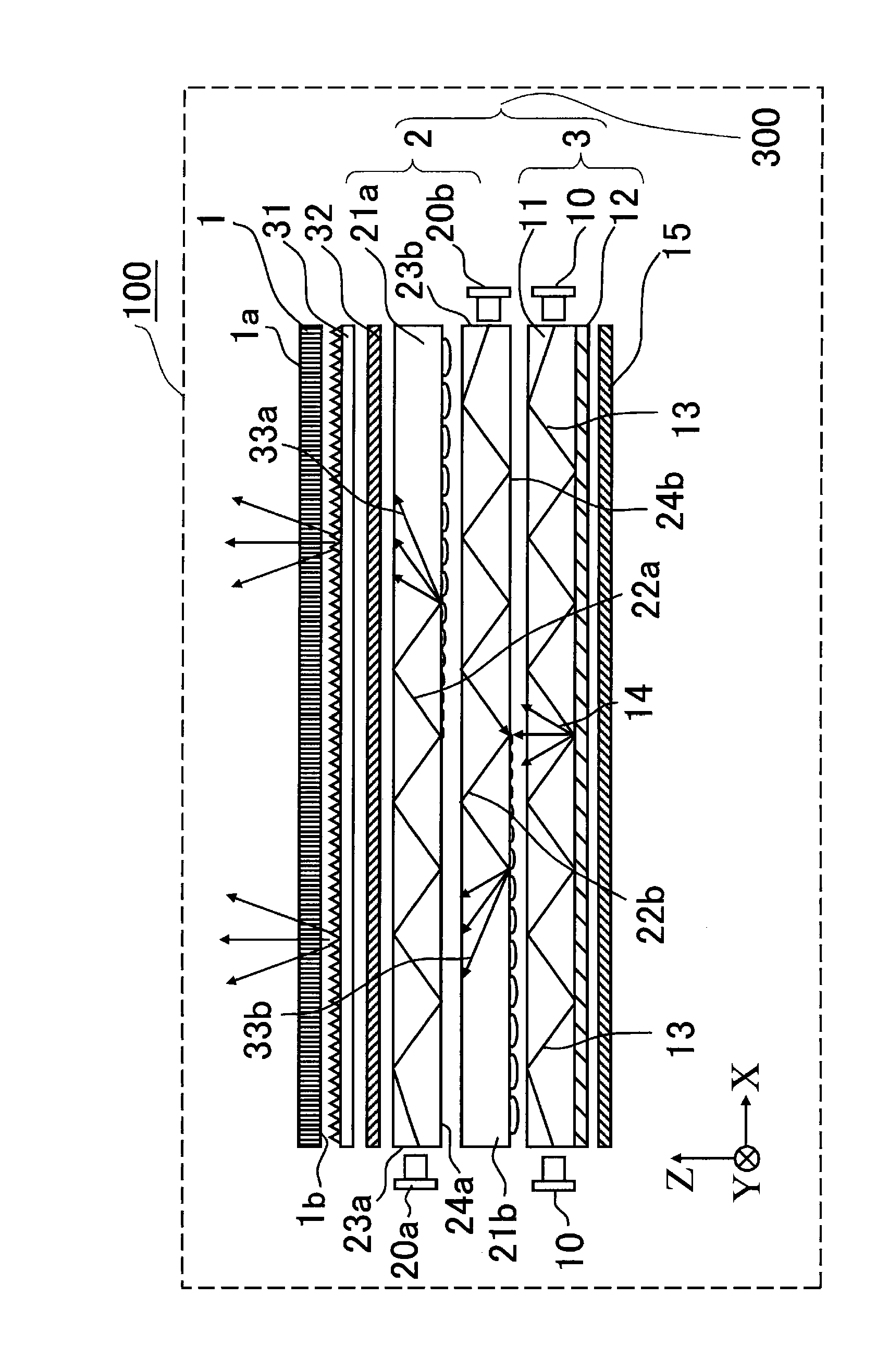
[0054] figure 1 It is a diagram schematically showing the configuration of a liquid crystal display device 100 that is a transmissive display device according to Embodiment 1 of the present invention. The backlight device according to Embodiment 1 includes a first backlight unit 2 and a second backlight unit 3 . For ease of understanding, the short side direction of the liquid crystal optical element 1 is defined as the Y-axis direction, the long side direction (direction perpendicular to the Y axis) of the liquid crystal optical element 1 is defined as the X-axis direction, and the direction perpendicular to the X-Y plane is defined as is the Z-axis direction. In addition, the display surface 1 a side of the liquid crystal display element 1 is defined as the +Z axis direction, and the upward direction of the liquid crystal display device (the upward direction when the screen of the liquid crystal display device 100 is installed facing the horizontal direction) is defined as ...
Embodiment approach 2
[0112] Figure 7 It is a diagram schematically showing the configuration of a liquid crystal display device (transmissive liquid crystal display device) 600 according to Embodiment 2 of the present invention. The backlight device according to Embodiment 2 includes a first backlight unit 2 and a second backlight unit 4 . The liquid crystal display device 600 of the second embodiment differs from the liquid crystal display device 100 of the first embodiment in that a second backlight unit 4 having a different structure is provided instead of the second backlight unit 3 of the liquid crystal display device 100 of the first embodiment. Except for this point, the liquid crystal display device 600 of the second embodiment is basically the same as the liquid crystal display device 100 of the first embodiment. exist Figure 7 , for the same as in Embodiment 1 ( figure 1 ) The result elements of the liquid crystal display device 100 described in ) are the same or the corresponding s...
Embodiment approach 3
[0117] Figure 8 It is a diagram schematically showing the configuration of a liquid crystal display device (transmissive liquid crystal display device) 700 according to Embodiment 3 of the present invention. The backlight device according to Embodiment 3 includes a first backlight unit 7 and a second backlight unit 3 . The liquid crystal display device 700 of the third embodiment is more suitable than the liquid crystal display device 100 of the first embodiment. In the liquid crystal display device 700 of Embodiment 3, the conditions of the light propagation portion are discussed in more detail and improved. In addition, in Figure 8 , the pair has the same as in Embodiment 1 ( figure 1 The structural elements used in ) are the same or the structural elements of the corresponding functions are marked with the same reference numerals. However, the structural elements described in detail in the third embodiment will be given new reference numerals, and the structural eleme...
PUM
| Property | Measurement | Unit |
|---|---|---|
| radius | aaaaa | aaaaa |
| refractive index | aaaaa | aaaaa |
Abstract
Description
Claims
Application Information
 - R&D
- Intellectual Property
- Life Sciences
- Materials
- Tech Scout
- Unparalleled Data Quality
- Higher Quality Content
- 60% Fewer Hallucinations
Browse by: Latest US Patents, China's latest patents, Technical Efficacy Thesaurus, Application Domain, Technology Topic, Popular Technical Reports.
© 2025 PatSnap. All rights reserved.Legal|Privacy policy|Modern Slavery Act Transparency Statement|Sitemap|About US| Contact US: help@patsnap.com