
Light-bulb voltage resistance detection device

A technology for pressure resistance detection and light bulbs, which is applied to measuring devices, using stable tension/pressure testing materials, instruments, etc., can solve the problems of easily damaged seals, bulb breakouts, and unsmooth driving of the ejector rod. Easy to damage, not easy to break, smooth moving effect

Inactive Publication Date: 2014-07-09
李家凌
View PDF1 Cites 0 Cited by
  • Summary
  • Abstract
  • Description
  • Claims
  • Application Information

AI Technical Summary

Problems solved by technology

[0002] The existing bulb withstand voltage detection device, as disclosed in patent 201010558497.0, includes an inflation detection part and a waste bulb cleaning part. The bulb is broken by the pressure gas and ejected from the bulb positioning position. Since the ejector rod is a movable part, its power needs to be provided by the power outside the air guide channel. Therefore, a sealing device needs to be provided between the ejector rod and the air guide channel. The prior art The advanced sealing device adopts a seal between the ejector rod and the ejector rod channel. For this type of sealing device, because the ejector rod needs to move relative to the seal, under high-frequency mutual friction, the seal is easily damaged, resulting in seal failure. Moreover, the seal The parts need to have enough pressure to act on the ejector rod to ensure sufficient sealing ability, which will inevitably increase the friction of the ejector rod movement, which will easily cause the ejector rod to not move smoothly and affect the cleaning of waste bulbs
In addition, the pressure gas is directly charged into the bulb through the gas guide channel, and the high-speed flowing gas can easily break the bulb

Method used


Image

  • Light-bulb voltage resistance detection device
  • Light-bulb voltage resistance detection device
  • Light-bulb voltage resistance detection device

Examples


Embodiment Construction

[0013] Now in conjunction with accompanying drawing and embodiment the present invention is described in further detail:

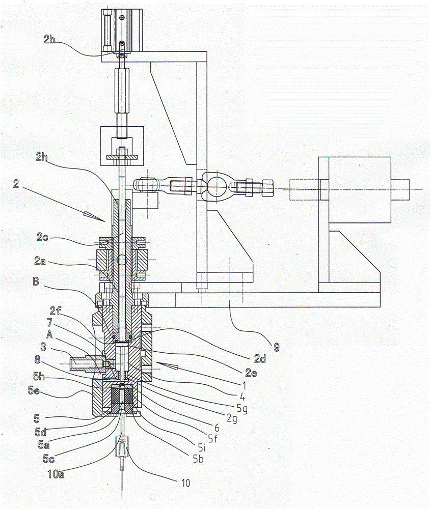
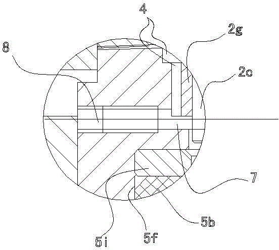
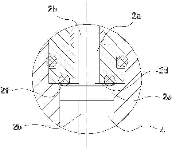
[0014] As shown in the figure, the present invention includes an inflation detection part 1 and a waste bulb cleaning part 2. The inflation detection part includes an air chamber 4 with a pressure gas inlet 3, a bulb sealing and fixing mechanism 5 located under the air chamber 4, and the air chamber 4 The bottom is provided with a stop surface 6, and the bulb sealing and fixing mechanism 5 includes a locking rubber particle 5b with a vertical perforation 5a in the middle of the bottom of the air chamber 4 and a locking rubber particle 5b located on both sides of the outlet of the air guide hole 5g. The following briquetting block 5d with the perforation 5c corresponding to the vertical perforation 5a of the locking colloidal particle 5b, the power moving mechanism 5e that drives the briquetting block 5d to move up and down, the waste bulb cleaning part 2 in...


PUM


Abstract

The invention relates to a light-bulb voltage resistance detection device which comprises a gas-inflation detecting part and a waste light-bulb cleaning part. The gas-inflation detecting part comprises a gas cavity and a light-bulb sealing and fixing mechanism; the gas cavity is provided with a pressure gas introduction opening; the light-bulb sealing and fixing mechanism is arranged below the gas cavity; a stop surface is arranged below the gas cavity; the light-bulb sealing and fixing mechanism comprises a locking colloidal particle, a pressing block and a power moving mechanism; the locking colloidal particle is arranged below the stop surface and provided with a vertical hole in the middle; the pressing block is arranged below the locking colloidal particle and provided with a hole which corresponds to the vertical hole of the locking colloidal particle; and the power moving mechanism is used for driving the pressing block to move up and down. The waste light-bulb cleaning part comprises a vertical guide hole and a mandril, wherein the guide hole is arranged above the gas cavity and communicated with the gas cavity; the mandril is arranged in the guide hole and driven by power. The light-bulb voltage resistance detection device is characterized in that: the lower end surface of the guide hole is provided with the stop surface, the mandril below the stop surface is provided with an externally-raised platform, and a sealing ring is arranged between the externally-raised platform and the stop surface. Compared with the prior art, the light-bulb voltage resistance detection device has the advantages that the sealing component is not easy to damage, the mandril moves smoothly, and the light bulb is not easy to burst due to the pressure gas.

Description

technical field [0001] The invention relates to a detection device for a light bulb. Background technique [0002] The existing bulb withstand voltage detection device, as disclosed in patent 201010558497.0, includes an inflation detection part and a waste bulb cleaning part. The bulb is broken by the pressure gas and ejected from the bulb positioning position. Since the ejector rod is a movable part, its power needs to be provided by the power outside the air guide channel. Therefore, a sealing device needs to be provided between the ejector rod and the air guide channel. The prior art The advanced sealing device adopts a seal between the ejector rod and the ejector rod channel. For this type of sealing device, because the ejector rod needs to move relative to the seal, under high-frequency mutual friction, the seal is easily damaged, resulting in seal failure. Moreover, the seal The parts need to have enough pressure to act on the ejector rod to ensure sufficient sealing ...

Claims


Application Information

Patent Timeline
Patent Type & Authority Patents(China)
IPC IPC(8): G01N3/12G01N3/02
Inventor 李家凌
Owner 李家凌
Learn More