
Construction method for cantilever assembly steel arches for cast-in-situ large-span concrete arch bridge

A construction method and technology for steel arches, which are applied in the field of cantilevered steel arches for arch bridges, can solve problems such as being difficult to implement and cumbersome, and achieve the effects of reasonable structure, advanced technology, and reliable fixing.

Active Publication Date: 2015-01-07
中交二公局第六工程有限公司
View PDF5 Cites 0 Cited by
  • Summary
  • Abstract
  • Description
  • Claims
  • Application Information

AI Technical Summary

Problems solved by technology

[0004] At the same time, it is too cumbersome to realize the horizontal sliding of the steel arch frame by using the traversing trolley or the pre-embedded slip, and it is not easy to realize

Method used


Image

  • Construction method for cantilever assembly steel arches for cast-in-situ large-span concrete arch bridge
  • Construction method for cantilever assembly steel arches for cast-in-situ large-span concrete arch bridge
  • Construction method for cantilever assembly steel arches for cast-in-situ large-span concrete arch bridge

Examples


Embodiment 1

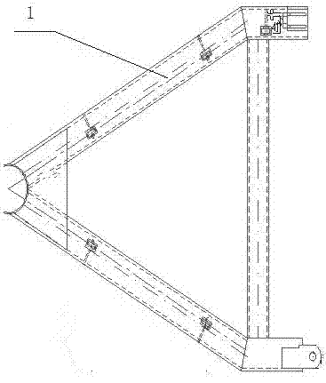
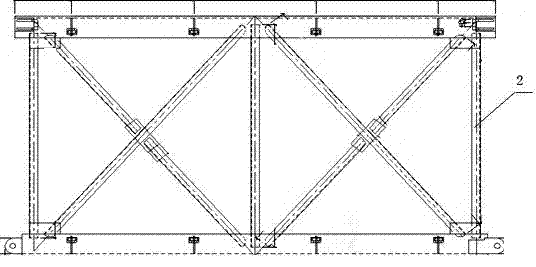
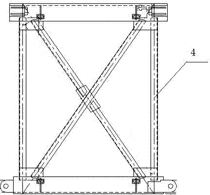
[0039] Construction method of cantilevered steel arch frame of cast-in-place long-span concrete arch bridge. The steel arch frame is composed of standard segment 2, adjustment segment 4, vault segment 3 and arch foot segment 1. The construction process mainly includes the steel arch Frame assembly and steel arch lateral movement are carried out simultaneously on both sides of the bridge span during construction. Its characteristics are: in the process of segmental connection, the horizontal system adopts the horizontal connection method, and the top surface of the arch frame and the ground adopt the flat connection method; The connection between the sections is connected by the lower chord pin shaft and the upper chord bolt connection; the specific construction is carried out according to the following steps:

[0040] Step 1, set the steel arch abutment; the steel arch abutment is a temporary abutment used to support the cast-in-place construction load. At the same time as the...

Embodiment 2

[0050] Taking the Fuxi River Bridge as an example, the Fuxi River Bridge is located on the eastern edge of the Guizhou Plateau. The bridge area is a plateau structure erosion-denudation low-middle mountain valley landform. The altitude near the bridge area is between 324.5 and 364m, with a relative height difference of 39m. The covering layer of the bridge area is cultivated soil, silty clay and alluvial-diluvial pebble soil. The upper structure of Fuxi River Bridge adopts 5×20m (prestressed concrete hollow slab) + 120m (reinforced concrete box arch) +2 ×20m (prestressed concrete hollow slab). The main hole of the lower structure adopts cast-in-place reinforced concrete abutment and cast-in-place concrete foundation, and reinforced concrete bent piers are set on the arch, and the junction piers No. The pile foundation and abutment foundation are cut and expanded foundations, and the abutments on both banks are gravity U-shaped abutments.

[0051]The steel arch is composed of ...


PUM


Abstract

The invention relates to the technology of cantilever assembly steel arches for an arch bridge, and particularly relates to a construction method for cantilever assembly steel arches for a cast-in-situ large-span concrete arch bridge. According to the invention, the steel arch is formed by jointing a standard segment, an adjustment segment, an arch crown segment and an arch springing segment, a construction process mainly comprises assembly for the steel arches and transversal movement for the steel arches which are performed simultaneously at the both sides spanned by the bridge during construction. The construction method is characterized in that a transversal system adopts a transversal connection mode, and an arch top surface and a floor adopt a flat connection mode during a segment connection process; the segments are connected by adopting bottom chord pin shafts and top chord bolts; and the specific construction is performed according to six steps including arrangement for a steel arch abutment, assembly for steel arch segments, arrangement for a transversal cable wind rope, pavement for a main arch ring, detachment for the steel arches, and transversal movement for the steel arches. The method is saving in material use, high in speed, reasonable in structure, advanced, economic and practical in technology, and suitable for arch bridges with different spans.

Description

technical field [0001] The invention relates to the technique of suspended steel arch frames for arch bridges, which is a construction method for the suspended steel arch frames of cast-in-situ large-span concrete arch bridges. Background technique [0002] There are many methods for splicing steel arch frames of existing arch bridges, such as the assembly method of universal rods, but the construction period of universal rod assembly is very long, and the construction process has a great impact on the environment, and it will be affected by environmental factors such as flood seasons. thus affecting the construction. [0003] In the cantilevered steel arch frame, the method of joint connection and pin connection of male and female joints is often used. Although this method is firmly connected, it is too rigid and cannot realize splicing and span adjustment. [0004] At the same time, the method of realizing the lateral sliding of the steel arch frame by using a traversing ...

Claims


Application Information

Patent Timeline
Patent Type & Authority Patents(China)
IPC IPC(8): E01D21/00E01D4/00
Inventor 邱玉兴张志荣马峰张利斌武云龙
Owner 中交二公局第六工程有限公司
Learn More