
A method and device for preventing oversupply of pluggable power supply

A power supply and oversupply technology, applied in the field of data communication, can solve the problems of downsizing, the switch software cannot update the bank matrix in time, and the power supply adjustment cannot be completed in time, so as to prevent oversupply.

Active Publication Date: 2016-04-20
NEW H3C TECH CO LTD
View PDF3 Cites 0 Cited by
  • Summary
  • Abstract
  • Description
  • Claims
  • Application Information

AI Technical Summary

Problems solved by technology

That is to say, during this process, the switch software cannot update the bank matrix in time, that is, the power adjustment in step 2 above cannot be completed in time
At this time, when a 715W power supply is inserted, because the bank matrix cannot be adjusted down in time, the POE chip will continue to supply power to the outside according to the original 1815W power, that is, the power supply of the two slots only provides 1530W power, while the POE The external power supply of the chip is 1815W. At this time, the POE power supply is overloaded. When the power supply is overloaded, it will automatically protect and cut off the power, so that the whole machine will be powered off.

Method used


Image

  • A method and device for preventing oversupply of pluggable power supply
  • A method and device for preventing oversupply of pluggable power supply
  • A method and device for preventing oversupply of pluggable power supply

Examples


Embodiment Construction

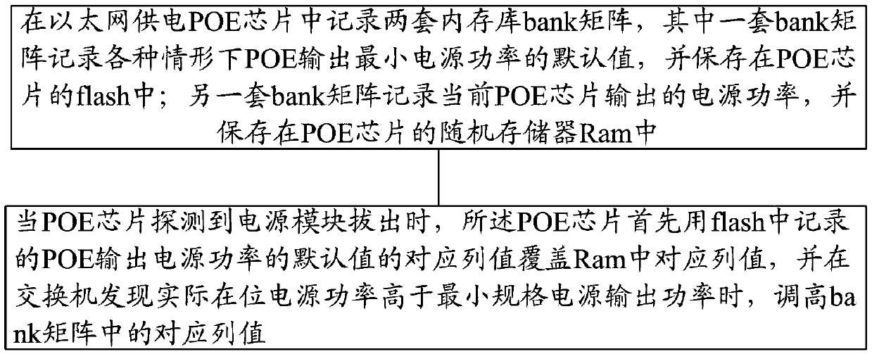
[0032] In order to achieve the purpose of the present invention, the core idea adopted by the present invention is to record two sets of memory bank bank matrices in the Power over Ethernet POE chip, and one bank matrix records the default value of the minimum power output of the POE chip in various situations, and Stored in the flash of the POE chip; another set of bank matrix records the power output of the current POE chip and stored in the RAM of the POE chip; when the POE chip detects that the power module is pulled out, the POE chip is used first The corresponding column value of the default value of the POE output power recorded in the flash covers the corresponding column value in the RAM, and when the switch finds that the actual on-site power is higher than the minimum specification power output power, increase the value of the corresponding column in the bank matrix .

[0033] In order to make the technical solution of the present invention clearer and more comprehensi...


PUM


Abstract

The invention discloses a method and a device for preventing over-supply of a pluggable power supply. According to the method, two sets of bank matrixes are recorded in a POE (Power over Ethernet) chip, wherein a default value of minimum power supply power output by the POE under various conditions is recorded in one set of matrix and is stored in a flash memory of the POE chip; power supply power output by the current POE chip is recorded in the other set of matrix and is stored in an Ram (Random access memory) of the POE chip; and when the POE chip detects that a power module is pulled out, the POE chip covers a corresponding column value in the Ram with a corresponding column value of the default value of the power supply power output by the POE recorded in the flash memory and the corresponding column value in the bank matrix is increased when a switch discovers that the actual in-situ power supply power is higher than the minimum specification power supply output power. According to the method and the device, network equipment can simultaneously support pluggable power supplies of various different powers, the power supply power is fully utilized, and meanwhile, a condition of over-supply of the power supply is prevented.

Description

Technical field [0001] The present invention relates to the technical field of data communication, in particular to a method and device for preventing oversupply when a POE (PoweroverEthernet, Power over Ethernet) equipment supports multiple pluggable power supplies of different powers. Background technique [0002] In order to improve the reliability of switch applications, most of the existing switches support pluggable power supply, which can be easily replaced when the power supply fails and provide redundant backup. This solution is currently widely used in data centers and other fields. [0003] Specifically, such as figure 1 As shown, the switch includes two pluggable power module slots 1 and 2. Assuming that slot 1 only supports 715W power supply, and slot 2 also only supports 715W power supply, you can set the bank (memory bank) matrix at this time (Bank matrix is ​​a function of the POE chip, used to set the combination of the power supply in each slot In this case, the...

Claims


Application Information

Patent Timeline
Patent Type & Authority Patents(China)
IPC IPC(8): H04L12/10
Inventor 毛桂全郑上闽杨利明
Owner NEW H3C TECH CO LTD
Learn More