
System and method for realizing automatic failure compensation for power battery

A power battery and automatic technology, applied in secondary battery repair/maintenance, electrical components, circuit devices, etc., can solve problems such as power battery system performance degradation, affecting vehicle operation and reliability, and increasing user costs

Active Publication Date: 2012-12-19
WEICHAI POWER CO LTD
View PDF6 Cites 12 Cited by
  • Summary
  • Abstract
  • Description
  • Claims
  • Application Information

AI Technical Summary

Problems solved by technology

[0004] In view of this, the main purpose of the present invention is to provide a system and method for automatic power battery failure compensation, which solves the problem of early failure of some battery modules in the battery modules in the prior art, which leads to the performance degradation of the power battery system, and further Issues that affect vehicle operation and reliability, and increase user costs

Method used


Image

  • System and method for realizing automatic failure compensation for power battery
  • System and method for realizing automatic failure compensation for power battery
  • System and method for realizing automatic failure compensation for power battery

Examples


Embodiment Construction

[0080] In order to make the above objects, features and advantages of the present invention more comprehensible, the embodiments of the present invention will be further described in detail below in conjunction with the accompanying drawings and specific implementation methods.

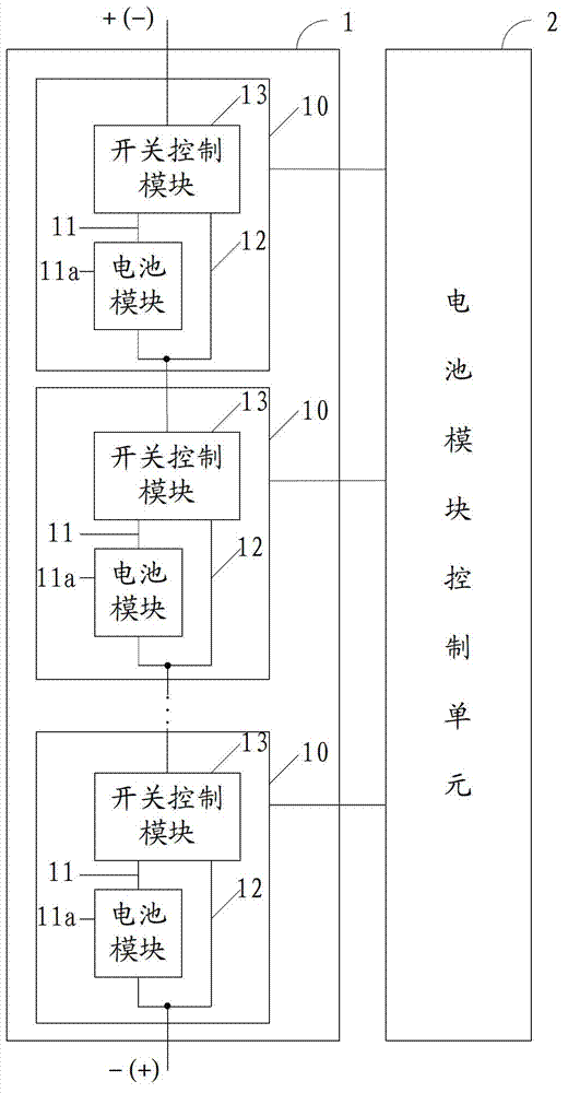
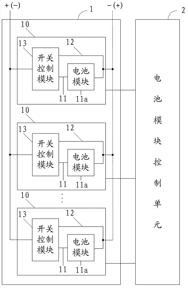
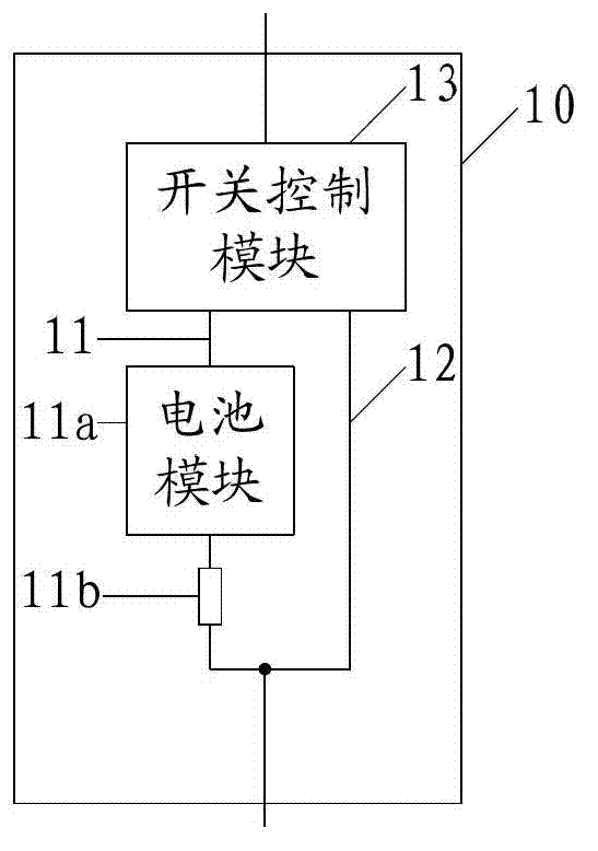
[0081] The present invention proposes a system for realizing automatic failure compensation of the power battery, aiming at the early failure of some battery modules in the battery module in the prior art, which leads to a decrease in the performance of the power battery system, which in turn affects the operation and reliability of the vehicle, and increases the number of users In terms of cost of use, the battery unit is marked as a working battery unit or a reserved battery unit. When the working battery unit fails, the battery module control unit controls the switch control module to isolate the failed battery unit from the battery module. The reserved battery unit is connected to the battery modul...


PUM


Abstract

The invention discloses a system for realizing automatic failure compensation for a power battery and realizes automatic compensation on an invalid unit of the power battery. The system comprises a battery module pack and a battery module control unit; the battery module pack comprises multiple battery units connected in series or in parallel, each battery unit comprises a first branch circuit, a second branch circuit and a switch control module, and each first branch circuit comprises a battery module; the battery module control unit is used for marking the battery units as working battery units or reserved battery units, and detecting the working state of one working battery unit and judging that the current working battery unit is invalid or not, if so, the invalid working battery unit is marked as an invalid battery unit, and any of the reserved battery unit as the working battery unit; a control instruction is transmitted to the working battery unit, the second branch circuit of the working battery unit is enabled to be switched off, and the first branch circuit of the working battery unit is enabled to be switched on; a control instruction is transmitted to a reserved battery unit, the first branch circuit of the reserved battery unit is enabled to be switched off, and the second branch circuit of the reserved battery unit is enabled to be switched on; and a control instruction is transmitted to the invalid battery unit, the first branch circuit of the invalid battery unit is enabled to be switched off, and the second branch circuit of the invalid battery unit is enabled to be switched on. The invention also discloses a method for realizing automatic failure compensation for the power battery.

Description

technical field [0001] The invention relates to the technical field of new energy vehicles, in particular to a system and method for realizing automatic failure compensation of power batteries. Background technique [0002] Traditional vehicles use petroleum as fuel as the power source, while new energy vehicles mostly use electricity as the main or auxiliary power source. Because new energy vehicles have less impact on the environment than traditional vehicles, their prospects are widely optimistic. At present, the main components of new energy vehicles to store electric energy are power batteries. In the existing technology, power batteries can be divided into three parts in structure: battery cells, battery modules and battery modules. Battery cells are the most basic work. The battery module is composed of several battery cells connected in series to form a series sequence of cells, and then composed of several cells connected in series in parallel; the battery module is...

Claims


Application Information

Patent Timeline
IPC IPC(8): H02J9/06H01M10/42
CPCY02E60/12Y02E60/10
Inventor 韩尔樑王宏宇张守中
Owner WEICHAI POWER CO LTD
Learn More