Lead connector

A wire connector, conductive connection technology, applied in the direction of multi-conductor connector, conductive connection, connection, etc., can solve the problems of complicated installation and production connection, complex connector or terminal structure, and unsatisfactory wiring effect, etc. To achieve the effect of simplifying wiring steps and operability

Active Publication Date: 2015-05-13
JIANGMEN KREALUX ELECTRICAL APPLIANCES
View PDF3 Cites 0 Cited by
  • Summary
  • Abstract
  • Description
  • Claims
  • Application Information

AI Technical Summary

Problems solved by technology

[0002] The existing wire connector is used as a terminal, and it is suitable for single-strand, multi-strand, fine multi-strand copper wires, and is an important connecting part for electrical connection. There are many kinds of wires, and the wiring cannot be done in one step. It is often necessary to disassemble the connector and use connectors or fixings, such as bolts, rivets, etc. to connect the wires to the connector. The installation and production connections are cumbersome and complicated, and the wiring process is increased. And reduce the efficiency of wiring, especially for connectors that need to connect flexible wires and hard wires, the process is more complicated and cumbersome; when the connector is connected to a wire, when the wire needs to be removed from the connector, it must be disassembled again connector, very inconvenient
[0003] Although, some people have invented connectors or terminal blocks that can be connected at one time, but this type of connector or terminal block has a complex structure, and the wiring effect is not ideal, and it does not have a one-step connection and one-step off-line structure. The service life is not long, and it fails to meet the diversified wiring requirements of today

Method used


Image

  • Lead connector
  • Lead connector
  • Lead connector

Examples


Embodiment 1

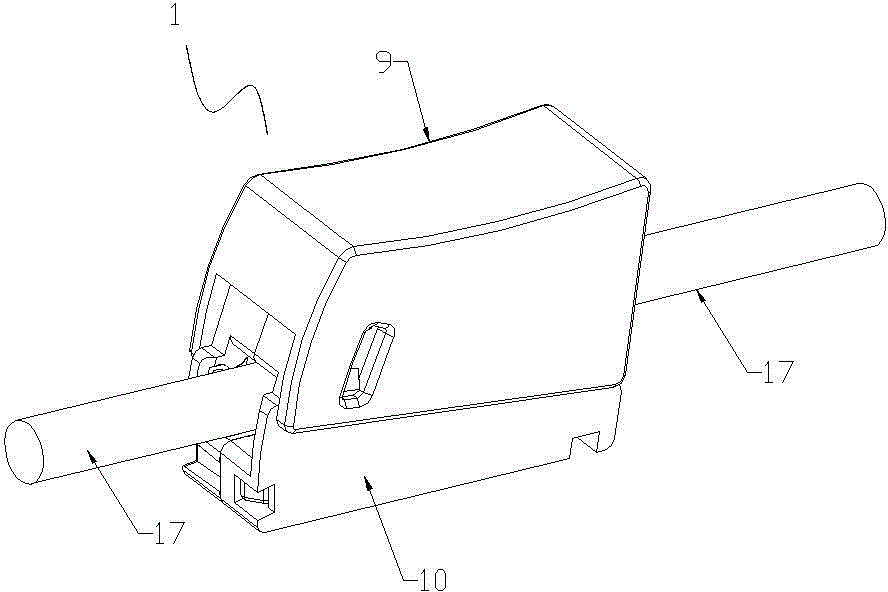
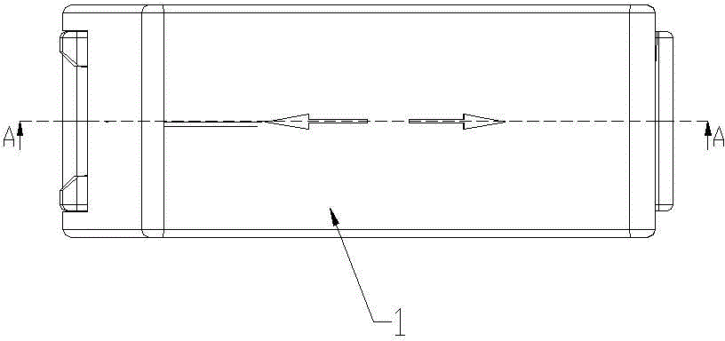
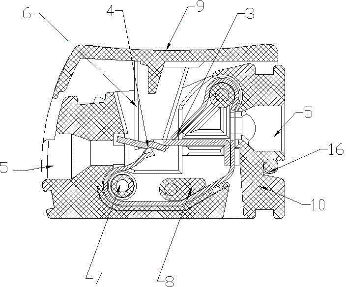
[0026] A wire connector described in Embodiment 1 of the present invention, such as figure 1 , figure 2 , image 3 , Figure 4 , Figure 5 , Image 6 , Figure 7 , Figure 8 , Figure 9 , Figure 10 As shown, it includes a housing 1 and a conductive connecting body placed in the housing. The conductive connecting body is composed of a cage-shaped elastic frame and a conductive piece fixed on the cage-shaped elastic frame. One end of the conductive sheet is fixed on the cage-shaped elastic frame, and the other end passes through the incision; the cage-shaped elastic frame is divided into two ends by the incision and corresponding to the conductive sheet, and the housing is provided with a channel corresponding to each port of the cage-shaped elastic frame. hole. Utilizing the design of the cutout and the conductive sheet, the cage-shaped elastic frame can connect flexible wires and hard wires at the same time. When the wire 17 is inserted into the connector for wiring...


PUM


Abstract

The invention discloses a lead connector which comprises a housing and a conductive connecting body arranged in the housing, wherein the conductive connecting body comprises a cage-shaped elastic frame and a conductive sheet fixed on the cage-shaped elastic frame, the cage-shaped elastic frame is provided with a notch for disconnecting the closing of the cage-shaped elastic frame, one end of the conductive sheet is fixed on the cage-shaped elastic frame, the other end of the conductive sheet penetrates through the notch, the cage-shaped elastic frame is divided into two ends by the notch and corresponds to the conductive sheet, and the housing is provided with through holes corresponding to ports of the cage-shaped elastic frame. The cage-shaped elastic frame can be connected with a soft wire and a hard wire by using designs of the notch and the conductive sheet, when a lead is inserted into the connector for wiring, the soft wire is clamped by one end of the cage-shaped elastic frame and the conductive sheet, the hard wire is clamped by the other end of the cage-shaped elastic frame and the conductive sheet, thus one-step wiring is realized; and during wire loosing, the housing is pressed, the lead is not clamped, thus one-step wire loosing can be realized.

Description

technical field [0001] The invention relates to a wire connector, in particular to a wire connector which uses a flexible wire and a hard wire to be directly plugged on the same connector to form a flexible and hard wire connection. Background technique [0002] The existing wire connector is used as a terminal, and it is suitable for single-strand, multi-strand, fine multi-strand copper wires, and is an important connecting part for electrical connection. There are many kinds of wires, and the wiring cannot be done in one step. It is often necessary to disassemble the connector and use connectors or fixings, such as bolts, rivets, etc. to connect the wires to the connector. The installation and production connections are cumbersome and complicated, and the wiring process is increased. And reduce the efficiency of wiring, especially for connectors that need to connect flexible wires and hard wires, the process is more complicated and cumbersome; when the connector is connect...

Claims


Application Information

Patent Timeline
Patent Type & Authority Patents(China)
IPC IPC(8): H01R11/00H01R11/01H01R11/03H01R4/48H01R4/62
CPCH01R4/22H01R4/48365
Inventor 饶小坡尹波青
Owner JIANGMEN KREALUX ELECTRICAL APPLIANCES
Why Eureka
Try Eureka