
Electric heating automatic temperature control heating module, and manufacturing method and installation method thereof

A production method and self-temperature control technology, applied in the direction of heating method, electric heating system, space heating and ventilation, etc., can solve the problems of scattered power lines, complicated wiring, wrong connection of positive and negative poles of wiring, etc., and achieve simple structure and convenient wiring Neat and beautiful effect

Pending Publication Date: 2020-01-17
苏州康碳地暖科技有限公司
View PDF1 Cites 0 Cited by
  • Summary
  • Abstract
  • Description
  • Claims
  • Application Information

AI Technical Summary

Problems solved by technology

[0005] First, the wiring is complicated, and it is necessary to lead the connecting wires from the edge of the board to the center of the board and from the center of the board to the edge of the board;
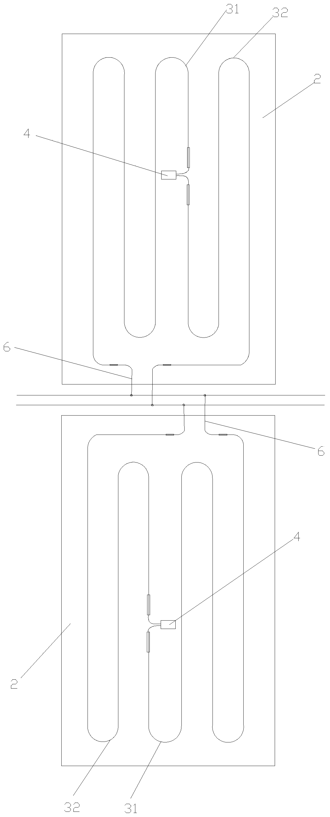
[0006] Second, the parts leading out the power lines on the module board are either too scattered, or they are concentrated in the center of the side, so that when multiple boards are laid, the wiring is easy to connect the positive and negative poles incorrectly.

Method used


Image

  • Electric heating automatic temperature control heating module, and manufacturing method and installation method thereof
  • Electric heating automatic temperature control heating module, and manufacturing method and installation method thereof
  • Electric heating automatic temperature control heating module, and manufacturing method and installation method thereof

Examples


Embodiment Construction

[0042] In order to enable those skilled in the art to better understand the solutions of the present invention, the following will clearly and completely describe the technical solutions in the embodiments of the present invention in conjunction with the drawings in the embodiments of the present invention. Obviously, the described embodiments are only It is an embodiment of a part of the present invention, but not all embodiments. Based on the embodiments of the present invention, all other embodiments obtained by persons of ordinary skill in the art without making creative efforts shall fall within the protection scope of the present invention.

[0043]It should be noted that the terms "first" and "second" in the description and claims of the present invention and the above drawings are used to distinguish similar objects, but not necessarily used to describe a specific sequence or sequence. It is to be understood that the data so used are interchangeable under appropriate c...


PUM


Abstract

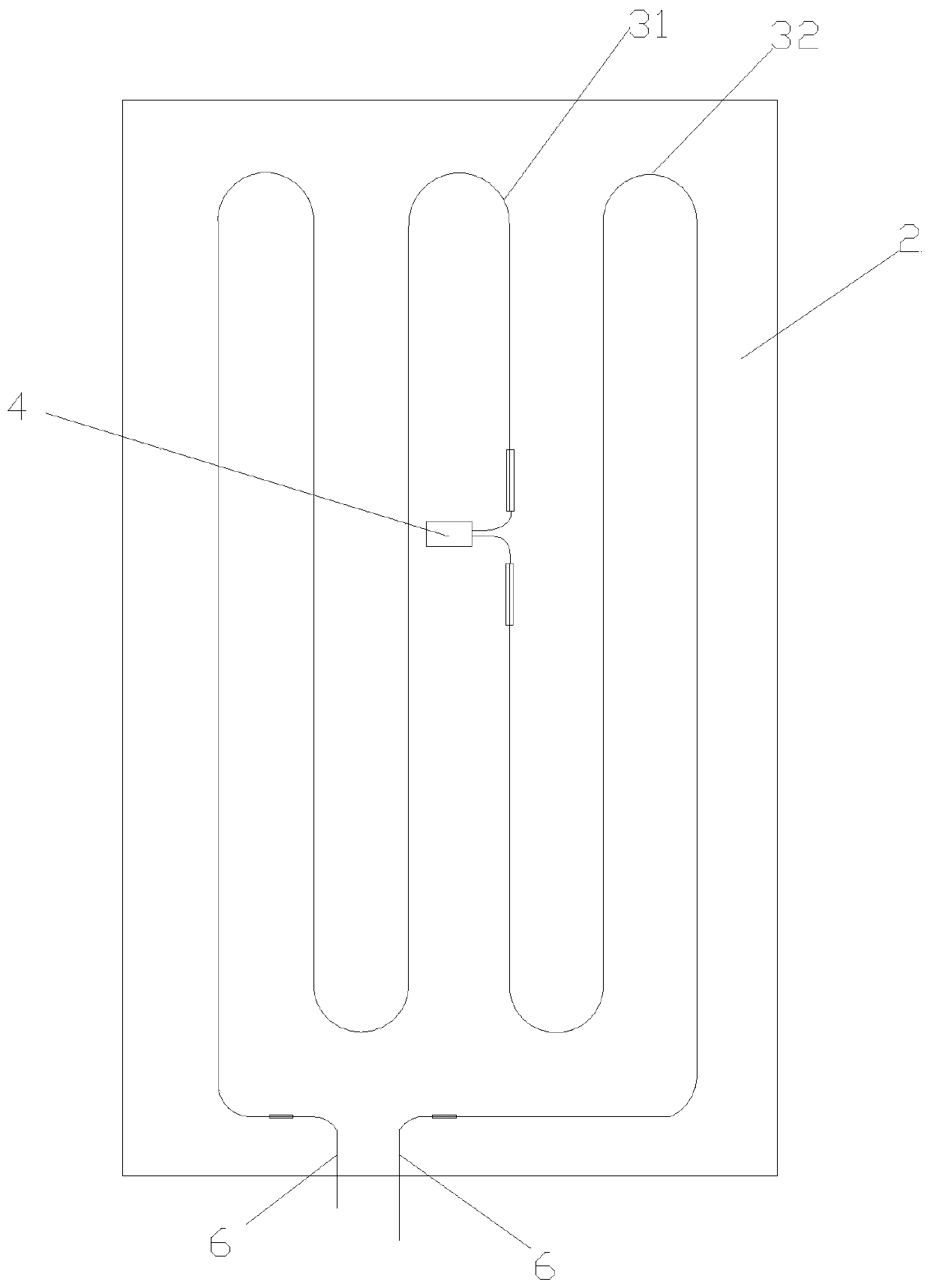
The invention discloses an electric heating automatic temperature control heating module, and a manufacturing method and installation method thereof. The electric heating automatic temperature controlheating module comprises a heat insulation plate, an aluminum plate, a first electric heating wire, a second electric heating wire and a heat protector temperature control switch. The heat insulationplate is provided with a first wire groove and a groove used for accommodating the heat protector temperature control switch. The aluminum plate is provided with a second wire groove and openings. The aluminum plate is arranged on the upper surface of the heat insulation plate. The second wire groove is clamped in the first wire groove. The first electric heating wire and the second electric heating wire are clamped in the second wire groove in sequence. One connecting end of the heat protector temperature control switch passes through the opening of the aluminum plate to be connected with one end of the first electric heating wire, and the other connecting end of the heat protector temperature control switch passes through the opening to be connected with one end of the second electric heating wire. The other ends of the first electric heating wire and the second electric heating wire are connected with an external AC power supply through power lines correspondingly. According to theelectric heating automatic temperature control heating module, the heating wires are located directly through the wire groove in the aluminum plate, the middle portion of a heating wire is divided into two parts and then can be connected with the heat protector temperature control switch. The wiring steps are simplified.

Description

technical field [0001] The invention relates to the field of electric heating modules, in particular to an electric heating self-temperature-controlling heating module and a manufacturing method and an installation method thereof. Background technique [0002] With the development of floor heating technology, heating floor heating has gradually entered thousands of households. However, the withstand temperature of the floor is about 70°C. If you go out, there will be a safety accident. Therefore, if the heating floor is not monitored, there is a greater potential safety hazard. [0003] The heating plate system usually installs a temperature detector indoors to measure the indoor air temperature. When the temperature measured by the temperature detector reaches a predetermined value, the power supply is cut off to adjust the indoor air temperature. However, when the heating plate is partially covered by clothes or other objects, the temperature of the covered part will ris...

Claims


Application Information

Patent Timeline
IPC IPC(8): F24D13/02F24D19/06F24D19/10
CPCF24D13/02F24D19/1096F24D19/062
Inventor 吴煜樊
Owner 苏州康碳地暖科技有限公司
Learn More