Method for real-time monitoring of remote equipment
A technology of real-time monitoring and remote equipment, applied in electrical program control, comprehensive factory control, comprehensive factory control, etc., can solve problems such as inability to monitor, and achieve the effect of quick troubleshooting, improved accuracy, and rich test methods.
Active Publication Date: 2012-12-19
SHANGHAI SPACEFLIGHT INST OF TT&C & TELECOMM
View PDF3 Cites 5 Cited by
- Summary
- Abstract
- Description
- Claims
- Application Information
AI Technical Summary
Problems solved by technology
[0003] The purpose of the present invention is to provide a method for real-time monito
Method used
View moreImage
Smart ImageViewing Examples
Examples
 PUM
 Abstract
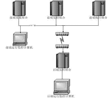
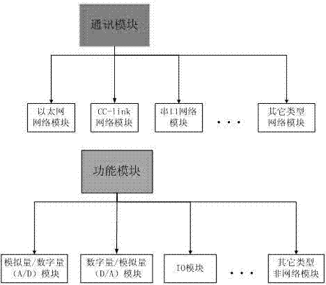
A method for real-time monitoring of remote equipment includes following steps: (1), establishing communication among remote automation combinations including a front-end launch control combination and a front-end data acquisition combination and a rear-end launch control combination positioned in a testing launch hall, and establishing communication between the rear-end launch control combination and a monitoring terminal; (2) dividing the communication among the remote automation combinations, the rear-end launch control combination and the monitoring terminal into at least a communication module and a function module, and establishing self-diagnosis processes corresponding to the communication module and the function module; and (3), gathering self-diagnosis data obtained during the self-diagnosis processes by the monitoring terminal, matching the self-diagnosis data with preset database configuration files, diagnosing out faults in real time, and automatically giving out fault solutions. Real-time monitoring and quick fault positioning of the preposed launch control combination and the preposed data acquisition combination which are positioned at a carrier rocket launch position and network passages connected with the preposed automation equipment can be realized in the testing control hall, so that system testing methods are enriched, and troubleshooting is more quick and convenient.
Description
technical field [0001] The invention relates to a field of real-time monitoring of remote automation equipment, especially a method for real-time monitoring of remote equipment in various fields including embedded software design of automation equipment, remote monitoring software design, real-time display of test data, and intelligent processing. Background technique [0002] In the measurement and control hall, there is no monitoring between the front-end launch control combination, the front-end data collection combination, and the network path connecting the front-end automation equipment at the launch vehicle launch tower, and it is impossible to monitor the real-time operation status of the remote automation equipment. Manual fault location requires a lot of manpower and time. Contents of the invention [0003] The purpose of the present invention is to provide a method for real-time monitoring of remote equipment, so as to solve the defect that cannot be monitored i...
Claims
Login to View More Application Information
Patent Timeline
 IPC IPC(8): G05B19/418
CPCY02P90/02
Inventor 蔡珂向军庄玮
Owner SHANGHAI SPACEFLIGHT INST OF TT&C & TELECOMM
Features
- R&D
- Intellectual Property
- Life Sciences
- Materials
- Tech Scout
- Unparalleled Data Quality
- Higher Quality Content
- 60% Fewer Hallucinations
Learn More Browse by: Latest US Patents, China's latest patents, Technical Efficacy Thesaurus, Application Domain, Technology Topic, Popular Technical Reports.
© 2025 PatSnap. All rights reserved.Legal|Privacy policy|Modern Slavery Act Transparency Statement|Sitemap|About US| Contact US: help@patsnap.com


