
Automatic self-description interface control document (ICD) encoder

An automatic encoder and self-describing technology, applied in the direction of instruments, simulators, program control, etc., can solve the problems of large workload, long test period, huge number of power distribution terminals, etc. The effect of a long test cycle

Inactive Publication Date: 2012-12-19
DALIAN POWER SUPPLY COMPANY STATE GRID LIAONING ELECTRIC POWER +1
View PDF5 Cites 2 Cited by
  • Summary
  • Abstract
  • Description
  • Claims
  • Application Information

AI Technical Summary

Problems solved by technology

[0002] The modification of telecontrol information point tables and communication parameters of traditional power distribution automation terminal equipment mainly depends on manual configuration. After the information point table is configured and the local test is correct, the master station and the factory station will conduct a point-by-point test. The probability of error is high and the test cycle is long. Generally, it takes more than 6 hours. In the power distribution automation system, the power distribution terminal The large number makes it very difficult to maintain and debug the distribution automation system
In addition, due to size limitations, most of the current distribution automation terminals use DSP (digital signal processors) and microcomputers as core processors to process remote signaling signal acquisition, telemetry and AC sampling, remote control output, local and remote communications and other tasks. , the remaining business processing capacity is very limited, it is difficult to complete the self-describing function of the device that meets the IEC 61850 standard, and adding this function to the original software code requires a lot of re-testing of the original function, and the workload is very heavy

Method used


Image

  • Automatic self-description interface control document (ICD) encoder

Examples


Embodiment Construction

[0008] The present invention will be further described below in conjunction with accompanying drawing:

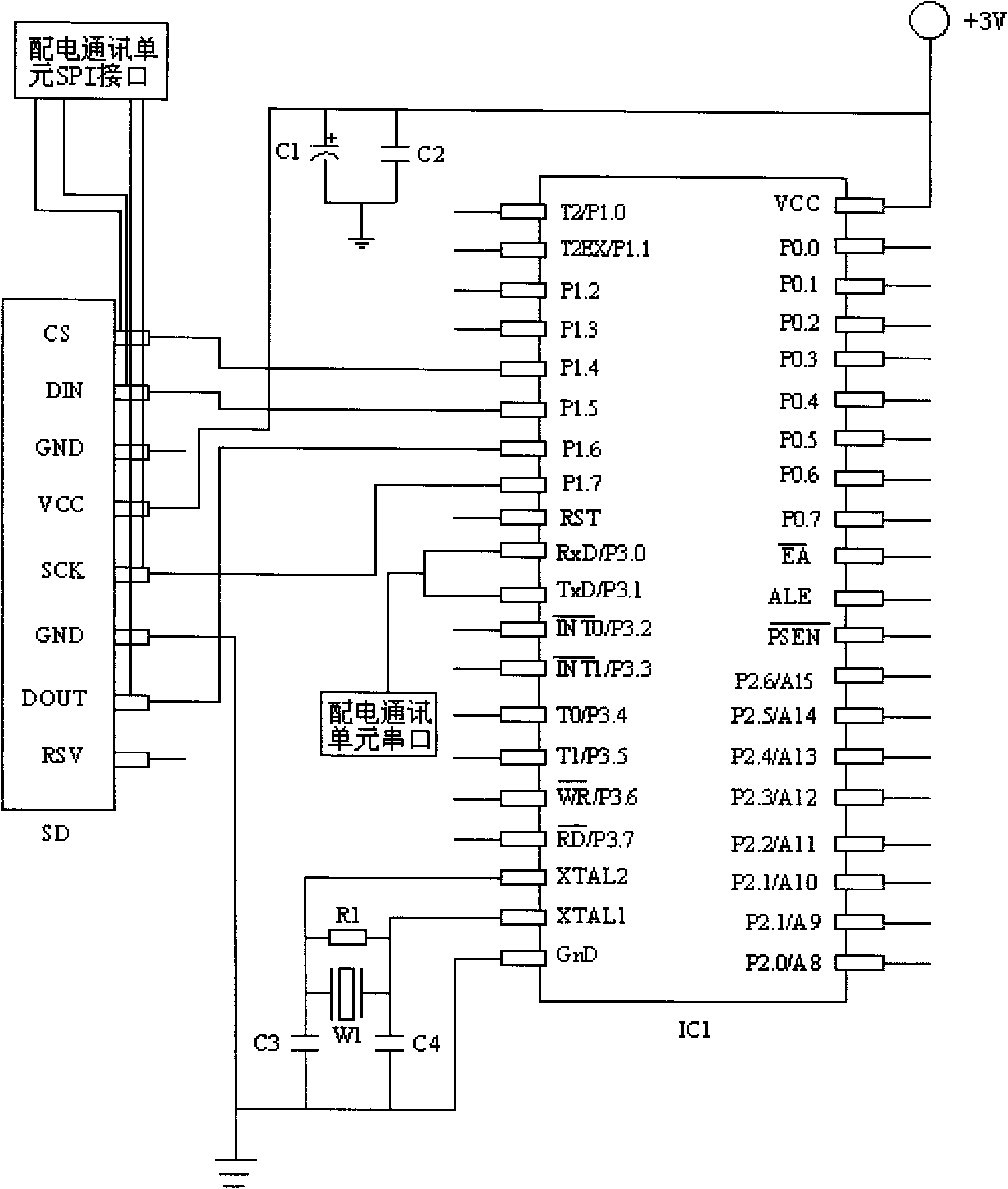
[0009] As shown in the figure, the single-chip microcomputer provided in this embodiment is a 40-pin 8051 single-chip microcomputer, and its P1.4 pin, P1.5 pin, and P1.6 pin work in the SPI interface mode, and the P1.4 pin is connected to the SD digital card. The CS pin is connected, and the SD digital card circuit will be activated when the output is low, and enter the chip selection state. The P1.5 pin is connected with the DIN pin of the SD digital card for reading the data in the SD card. The P1.6 pin is connected with the DOUT pin of the SD digital card, and is used to write data into the SD digital card. The P1.7 pin is connected with the SCK pin of the SD digital card to provide an external clock for the SD card circuit. Pin P3.0 and pin P3.1 of the single chip microcomputer are respectively connected with the serial port sending terminal and receiving terminal of ...


PUM


Abstract

The invention relates to an automatic self-description interface control document (ICD) encoder, comprising a single chip microcomputer, characterized in that the encoder consists of a single chip microcomputer, a secure digital(SD) card, a clock oscillation circuit and a power filter circuit, the single chip microcomputer being connected with the SD card, writing date into the SD card and also being connected with the serial port of a distribution automation terminal communication unit, the SD card being connected with the serial peripheral interface(SPI) of the distribution automation terminal communication unit, the power filter circuit being connected between the power source and the SD card, and the clock circuit being connected with the single chip microcomputer. Data as remote signaling data, remote measurement data and remote control data, sampled by the distribution automation terminal is automatically generated to be self-description ICD documents meeting the International Electrotechnical Commission (IEC) 61850 standard, which avoids the defects of low work efficiency, high malfunction probability and long testing period, resulted from the allocation of manual production remote information point table and manual test point table. The encoder is simple in the structure, convenient in installation and use, and reliable in performance.

Description

technical field [0001] The invention relates to a power distribution automation terminal equipment for a power grid, in particular to a self-describing ICD file automatic encoder. Background technique [0002] The modification of telecontrol information point tables and communication parameters of traditional power distribution automation terminal equipment mainly depends on manual configuration. After the information point table is configured and the local test is correct, the master station and the factory station will conduct a point-by-point test. The probability of error is high and the test cycle is long. Generally, it takes more than 6 hours. In the power distribution automation system, the power distribution terminal The huge number makes it very difficult to maintain and debug the distribution automation system. In addition, due to size limitations, most of the current distribution automation terminals use DSP (digital signal processors) and microcomputers as core ...

Claims


Application Information

Patent Timeline
IPC IPC(8): G05B19/042
Inventor 石文江阴晓光
Owner DALIAN POWER SUPPLY COMPANY STATE GRID LIAONING ELECTRIC POWER
Learn More