
Method, device and system for measurement of oil injection volume

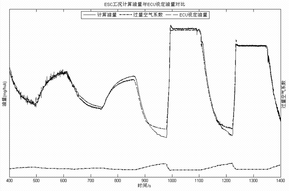
A measurement method and technology of fuel injection quantity, applied in the field of fuel injection quantity measurement method, device and system, can solve the problems that the fuel injection quantity cannot be obtained, the operation of the diesel engine cannot be well controlled, etc., and the actual fuel injection quantity is accurate and calculated The effect of simple method

Active Publication Date: 2012-12-19
WEICHAI POWER CO LTD
View PDF4 Cites 8 Cited by
  • Summary
  • Abstract
  • Description
  • Claims
  • Application Information

AI Technical Summary

Problems solved by technology

However, the ECU electronic control unit in the prior art cannot obtain the actual fuel injection quantity, and cannot control the diesel engine to run better.

Method used


Image

  • Method, device and system for measurement of oil injection volume
  • Method, device and system for measurement of oil injection volume
  • Method, device and system for measurement of oil injection volume

Examples


no. 1 example

[0070] see figure 1 , which is a flow chart of the first embodiment of the method for measuring fuel injection quantity provided by the present invention, the method includes:

[0071] S101, collecting and obtaining the concentration of oxygen in the exhaust gas.

[0072] In the first embodiment of the present invention, the concentration of oxygen in the exhaust gas is collected by the first collection unit. Specifically, the first collection unit is a nitrogen and oxygen sensor. For example, the SCR system is generally used in high-pressure common rail diesel engines, and the nitrogen oxygen sensor (NOx sensor) is one of the necessary sensors. The O2 content of the exhaust gas can thus be measured with the NOx sensor.

[0073] S102. Calculate an excess air factor by using the concentration of oxygen in the exhaust gas.

[0074] Wherein, the excess air coefficient is calculated according to the following formula:

[0075] λ = ...

no. 2 example

[0083] see figure 2 , which is a flow chart of the second embodiment of the method for measuring fuel injection quantity provided by the present invention, the method includes:

[0084] S201, collecting and obtaining the concentration of oxygen in the exhaust gas.

[0085] Specifically, the concentration η of oxygen in the exhaust gas is collected by a nitrogen and oxygen sensor 1 .

[0086] S202, measure the intake air temperature, the intake air pressure, and the engine speed.

[0087] In this specific embodiment of the present invention, the intake air temperature t is measured by the intake air temperature sensor 1 ; Use the intake pressure sensor to measure the intake pressure P; use the engine speed sensor to measure the engine speed n.

[0088] Those skilled in the art can understand that the order of step S201 and step S202 can be reversed or executed in parallel.

[0089] S203. Calculate an excess air coefficient by using the concentration of oxygen in the exhau...


PUM


Abstract

The invention relates to the field of diesels, in particular to a method, a device and a system for measurement of oil injection volume. The method includes: acquiring the concentration of oxygen in waste gas; calculating to obtain an excess air coefficient according to the concentration of oxygen in waste gas; calculating to obtain single-cylinder per cycle air inlet volume; and calculating to obtain actual oil injection volume according to the excess air coefficient and the single-cylinder per cycle air inlet volume, wherein the actual oil injection volume is equal to a product which is obtained in a way that the single-cylinder per cycle air inlet volume is divided by a product of the excess air coefficient and a stoichiometric ratio to obtain a specific value, and the specific value is multiplied by an oil volume correction coefficient to obtain the product. Using the method can realize calculation of the actual oil injection volume without increasing cost of an electronic control system, calculation results are accurate and reliable, valid input parameters are provided for control of a diesel, and an electronic control unit can more conveniently control the diesel to operate.

Description

technical field [0001] The invention relates to the field of diesel engines, in particular to a method, device and system for measuring fuel injection quantity. Background technique [0002] The increasingly severe energy crisis has made diesel engines the focus of attention in the internal combustion engine industry. Compared with gasoline engines, diesel engines have advantages such as reduced exhaust emissions, low fuel consumption, and good acceleration performance at low speeds, so they have been used more and more. With the improvement of emission standards, the development of diesel fuel injection system has also been promoted, and the diesel fuel injection system has developed from a mechanical control system to an electronic control system. The current diesel fuel injection system is controlled by ECU (Electronic Control Unit, electronic control unit). The set fuel injection volume of the engine has a great relationship with the calibration accuracy. As the engine s...

Claims


Application Information

Patent Timeline
IPC IPC(8): G01F22/00
Inventor 孙少军佟德辉桑海浪李志杰岳广照张展腾吕志华
Owner WEICHAI POWER CO LTD
Learn More