
Optical fiber sensing system based on phase-shifted optical fiber grating

A phase-shifting fiber grating and fiber sensing system technology, applied in the field of optical sensors, can solve the problems of difficult promotion and application, high system cost, and achieve the effects of increasing line width, ensuring optical power and saving costs.

Active Publication Date: 2012-12-19
INST OF SEMICONDUCTORS - CHINESE ACAD OF SCI
View PDF4 Cites 26 Cited by
  • Summary
  • Abstract
  • Description
  • Claims
  • Application Information

AI Technical Summary

Problems solved by technology

[0004] The wavelength demodulation method has been proposed in the prior art, however, the wavelength demodulation system of the prior art needs to be applied to a high-resolution spectrometer or a narrow linewidth tunable laser, the system cost is high, and it is difficult to popularize and apply

Method used


Image

  • Optical fiber sensing system based on phase-shifted optical fiber grating
  • Optical fiber sensing system based on phase-shifted optical fiber grating

Examples


Embodiment Construction

[0021] In order to make the object, technical solution and advantages of the present invention clearer, the present invention will be described in further detail below in conjunction with specific embodiments and with reference to the accompanying drawings.

[0022] It should be noted that, in the drawings or descriptions of the specification, similar or identical parts all use the same figure numbers. And in the accompanying drawings, it is marked for simplicity or convenience. Furthermore, implementations not shown or described in the accompanying drawings are forms known to those of ordinary skill in the art. Additionally, while illustrations of parameters including particular values ​​may be provided herein, it should be understood that the parameters need not be exactly equal to the corresponding values, but rather may approximate the corresponding values ​​within acceptable error margins or design constraints.

[0023] Please refer to figure 1 , figure 1 It is an opti...


PUM

PropertyMeasurementUnit
Line widthaaaaaaaaaa
Center wavelengthaaaaaaaaaa
Line widthaaaaaaaaaa

Abstract

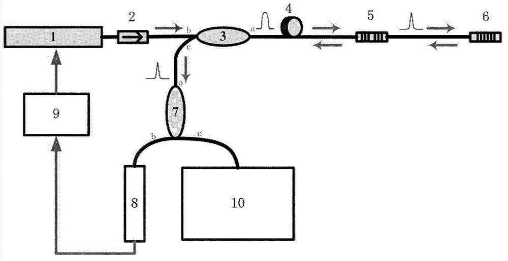
The invention provides an optical fiber sensing system based on a phase-shifted optical fiber grating. The optical fiber sensing system comprises a semiconductor laser light source, a first coupler, the phase-shifted optical fiber grating, a fiber Bragg grating, a second coupler and a wavelength demodulation instrument, wherein the semiconductor laser light source generates a laser with preset wavelength width; the first coupler is used for coupling the laser with the preset wavelength width to the phase-shifted optical fiber grating and coupling a signal laser reflected back by the fiber Bragg grating to the second coupler; a transmission window of the phase-shifted optical fiber grating changes along with change of external physical quantity of the phase-shifted optical fiber grating, and transmitted portions of the laser passing through the phase-shifted optical fiber grating form the signal laser with wavelength narrower than the preset wavelength; the fiber Bragg grating is used for reflecting the signal laser, and the reflected signal laser is transmitted to the first coupler by the aid of the phase-shifted optical fiber grating; the second coupler is used for coupling the signal laser to the wavelength demodulation instrument; and the wavelength demodulation instrument is used for demodulating the signal laser to obtain the external physical quantity of the phase-shifted optical fiber grating. The optical fiber sensing system based on the phase-shifted optical fiber grating does not need a high-resolution spectrograph or a narrow-linewidth tunable laser, so that cost is greatly saved.

Description

technical field [0001] The invention relates to the technical field of optical sensors, in particular to an optical fiber sensing system based on a phase-shifting optical fiber grating. Background technique [0002] Fiber Bragg Grating (FBG for short) is made by utilizing the photosensitivity in the optical fiber, and the refractive index of the fiber core is periodically modulated to form a narrow-band (transmission or reflection) filter or mirror. When it is affected by physical quantities such as ambient temperature and pressure, its central wavelength will change, so fiber gratings can be used as sensors to measure changes in external physical quantities. Fiber Bragg grating sensing system has the advantages of anti-electromagnetic interference, corrosion resistance, stable chemical performance, small size, light weight, etc., and can be widely used in measuring temperature, pressure, strain, acceleration, etc., and has been widely used in large-scale structural building...

Claims


Application Information

Patent Timeline
IPC IPC(8): G01D5/26
Inventor 徐团伟李芳刘育梁
Owner INST OF SEMICONDUCTORS - CHINESE ACAD OF SCI
Learn More