
Method for recovering surplus heat source energy by using flash evaporator

A technology of flash evaporator and heat source, which is applied in the field of using flash evaporator to recover excess heat source energy. It can solve the problems of ineffective use of heat, unreasonable recycling, and complex waste heat recovery system. It achieves no rotating parts, strong practicability, highly operable effect

Inactive Publication Date: 2012-12-19
BEIJING UNIV OF TECH
View PDF7 Cites 7 Cited by
  • Summary
  • Abstract
  • Description
  • Claims
  • Application Information

AI Technical Summary

Problems solved by technology

[0005] 2. In a thermal system, there are often other waste heat sources, and the heat is often not used effectively, and the heat is wasted in vain
Even if the heat from other waste heat sources is recycled, it needs to be put into other recovery devices (such as heat exchangers), which makes the waste heat recovery system complicated
[0006] To sum up, in the process of recovering waste heat in the existing flash evaporator, the amount of steam flashed by the liquid waste heat source in the flash evaporator is not high, and the flash evaporation effect is poor; while the heat of other waste heat sources in the process is not recovered reasonably use

Method used


Image

  • Method for recovering surplus heat source energy by using flash evaporator
  • Method for recovering surplus heat source energy by using flash evaporator

Examples


Embodiment Construction

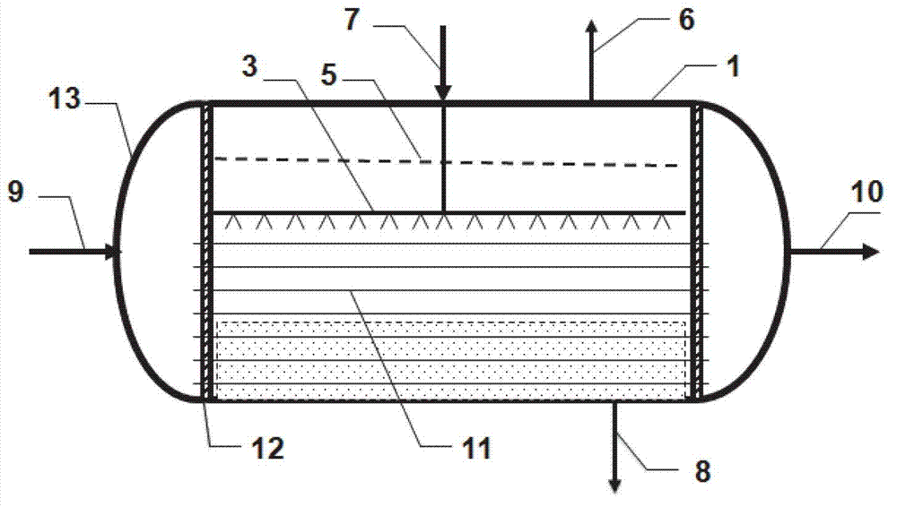
[0032] The specific implementation method is: the waste heat source B enters the heat exchange tube 11 at the lower part of the flasher from the waste heat source B inlet 9, releases heat to heat the waste heat source A liquid sprayed outside the heat exchange tube, and discharges it from the waste heat source B outlet 10 after releasing heat and cooling down Flash evaporator; the residual heat source A enters the spray pipe 3 from the inlet of the residual heat source A, and after forming droplets, due to expansion and pressure reduction, the liquid of the residual heat source A flashes a part of saturated steam under low pressure; the remaining residual heat source A liquid is in the form of fine liquid The form of droplets is sprayed on the surface of the heat exchange tube 11. After absorbing the heat of the waste heat source B in the heat transfer tube, a part of the liquid of the waste heat source A is vaporized into saturated steam, and the saturated steam is drawn out fr...


PUM


Abstract

The invention relates to a method for recovering surplus heat source energy by using a flash evaporator and belongs to the field of the flash evaporator. The flash evaporator comprises a cylinder, a spraying pipe, a steam-liquid separator, a steam outlet, a surplus heat source inlet A, a surplus heat source outlet A, a surplus heat source inlet B, a surplus heat source outlet B, a heat exchange pipe, a pipe plate and end sockets, wherein the flash evaporator is horizontally arranged; the end sockets are arranged at the two ends of the cylinder; the cylinder and the end sockets are connected through the pipe plate; the steam-liquid separator, the spraying pipe and the heat exchange pipe are fixed on the pipe plate; the steam-liquid separator is located in an upper space of the flash evaporator; the spraying pipe is arranged in a middle space; the heat exchange pipe is arranged in a lower space; a part of the heat exchange pipe is soaked in surplus heat source liquid A; the surplus heat source inlet A is arranged on the upper part of the cylinder; the surplus heat source outlet A is arranged on the lower part of the cylinder; the surplus heat source inlet A is connected with the spraying pipe; the surplus heat source inlet B is arranged at one end of the cylinder; and the surplus heat source outlet B is arranged at the other end of the cylinder. The flash evaporator can simultaneously recover the surplus heat source energy and can obviously increase the flashing evaporation effect.

Description

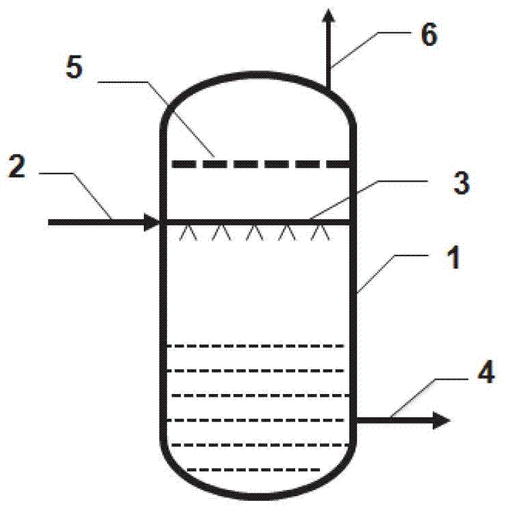
technical field [0001] The core of the present invention proposes a method of using a flash evaporator to recover excess heat energy, which is mainly used for the recovery of waste heat from multiple heat sources. More saturated steam can be produced in the flash evaporator, and the flash evaporation effect can be significantly improved. Background technique [0002] figure 1 It is a structural schematic diagram of an existing flash evaporator, and its structure includes: a cylinder body 1, a liquid inlet 2 is arranged on the upper side wall of the cylinder body, the liquid inlet 2 is connected to a spray pipe 3, and a liquid outlet is arranged on the lower side wall of the cylinder body 4. There is a steam outlet 6 on the top of the cylinder, and a vapor-liquid separator 5 on the upper part of the flash evaporator. The waste heat source enters the spray pipe 3 from the liquid inlet 2, and after spraying into fine droplets, the capacity is expanded and the pressure is reduc...

Claims


Application Information

Patent Timeline
IPC IPC(8): F22B3/04F22B1/16
Inventor 刘中良张克舫刘兴伟
Owner BEIJING UNIV OF TECH
Learn More