
Magnetic powder clutch applying permanent magnet material

A technology of magnetic powder clutch and permanent magnet material, applied in the field of clutch, can solve the problems of increasing the rotational inertia of the engine flywheel, decreasing the acceleration power of the engine, complex structure and control system, etc., achieving simple structure, increasing effective area and convenient control. Effect

Inactive Publication Date: 2012-12-19
NANJING UNIV OF SCI & TECH
View PDF11 Cites 8 Cited by
  • Summary
  • Abstract
  • Description
  • Claims
  • Application Information

AI Technical Summary

Problems solved by technology

However, when the magnetic powder clutch needs to be supplied with current, a certain energy loss is generated, which reduces its economy.
The national utility model patent 032476124 application proposes a composite clutch for vehicles, which comprehensively utilizes the respective advantages of friction plate clutches and magnetic powder clutches, reduces the vibration and impact of vehicle engagement, and reduces energy consumption. However, the structure and control system are complicated, the practicability is poor, and the The moment of inertia of the flywheel of the engine is increased, so that the acceleration power of the engine is reduced

Method used

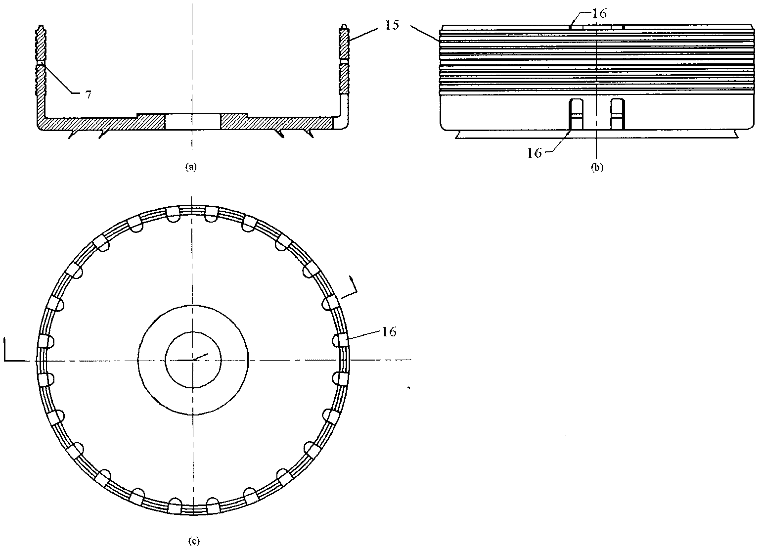
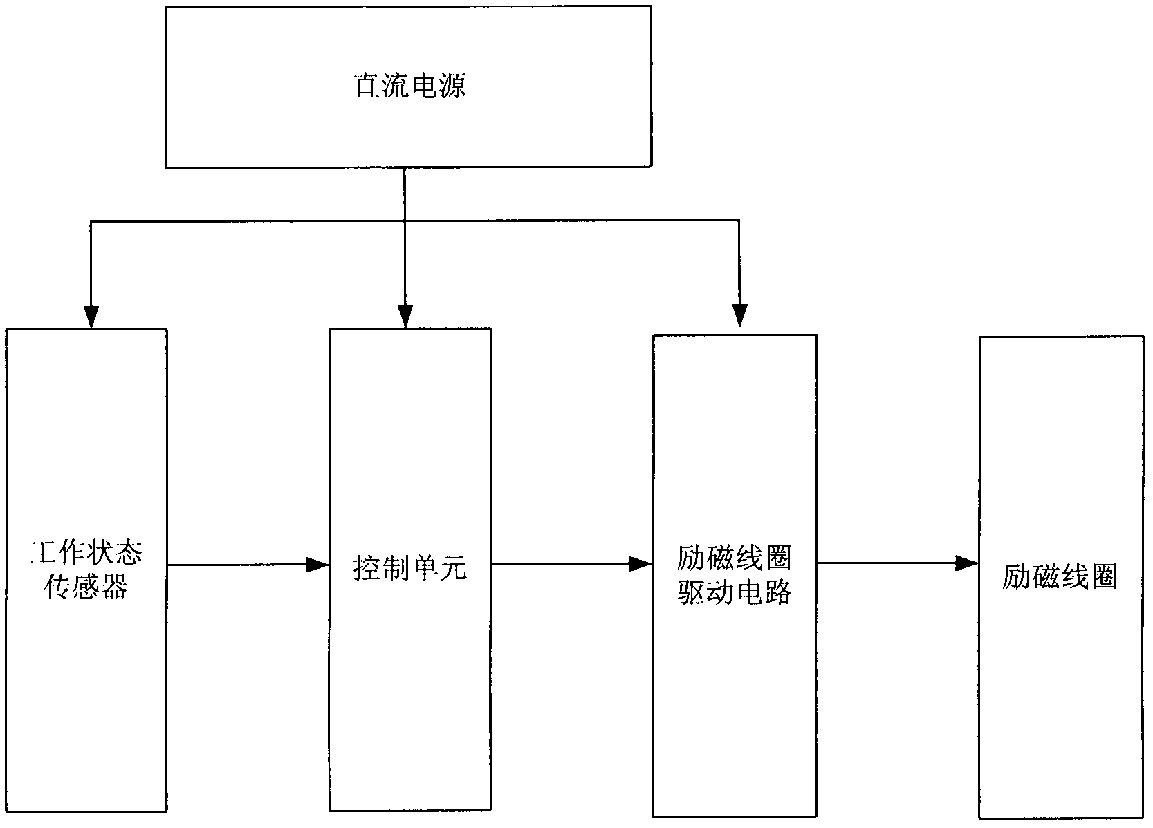

Image

  • Magnetic powder clutch applying permanent magnet material
  • Magnetic powder clutch applying permanent magnet material
  • Magnetic powder clutch applying permanent magnet material

Examples


Embodiment Construction

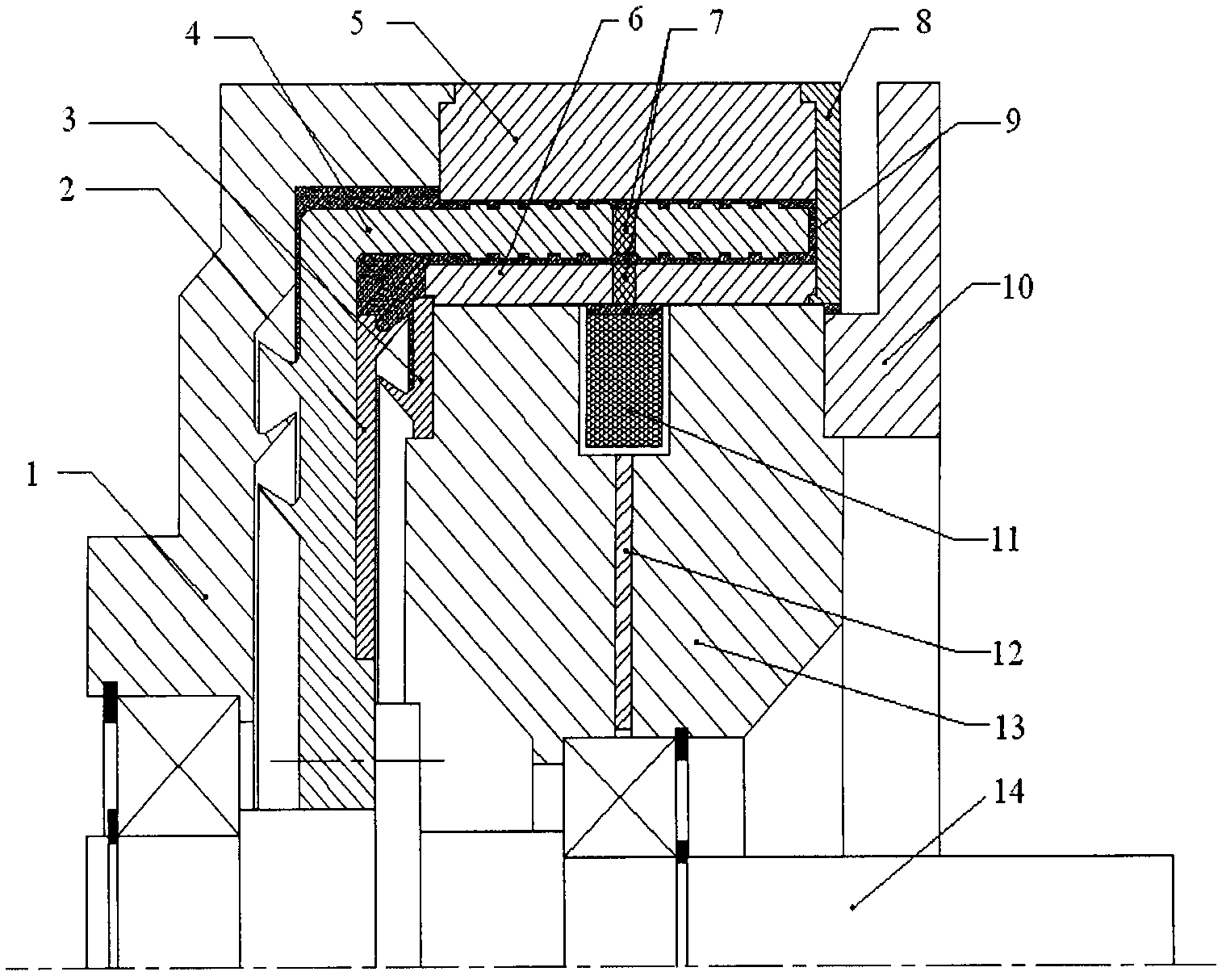
[0012] The present invention applies the magnetic powder clutch of permanent magnet material, figure 1 Its structural diagram shows that the permanent magnet 12 and the excitation coil 11 are embedded in the yoke 13 to form a permanent magnet-electromagnetic hybrid magnetic circuit structure. The permanent magnet 12 and the excitation coil 11 divide the yoke 13 into two parts in the axial direction. The permanent magnet 12 is located radially inside the excitation coil 11 . The yoke 13 is supported on the output shaft 14 through a bearing, and a magnetic powder stop ring 3 is installed on the end surface of the yoke 13 adjacent to the driven rotor 4 . The yoke 13 is connected with the flange 10, and the flange 10 is fixed on the base. The permanent magnet 12 can adopt NdFeB material.

[0013] The inner driving rotor 6 and the outer driving rotor 5 are connected as a whole through a connecting ring 8 to form a clutch driving rotor. The end cover 1 is connected with the oute...


PUM


Abstract

The invention discloses a magnetic powder clutch applying permanent magnet material. A permanent magnet and an excitation coil are embedded in a magnetic yoke for constituting a permanent magnet-electromagnetic hybrid type magnetic circuit structure; the magnetic yoke is bisected into two parts along the axial direction by the permanent magnet and the excitation coil, the permanent magnet is positioned at the radial inner side of the excitation coil, and the magnetic yoke is supported on an output shaft through a bearing; a second magnetic powder baffle ring is arranged on the end surface, which is adjacent to a driven rotor, of the magnetic yoke; the magnetic yoke is connected with a flange plate; and the flange plate is fixed on a baseframe; an inner driving rotor and an outer driving rotor are connected into a whole through a connecting ring for constituting the driving rotor of the clutch; the driven rotor is connected with the output shaft through a key; and a first magnetic powder baffle ring is arranged on the end surface, which is adjacent to the magnetic yoke, of the driven rotor; magnetic isolation rings are welded on the inner driving rotor and the driven rotor; and the inner driving rotor, the driven rotor and the outer driving rotor are arranged on the same axial line. The magnetic powder clutch disclosed by the invention has the advantages that structure is simple, control is convenient, moment of inertia of driving parts is moderate, and energy conservation, emission reduction and consumption reduction are realized.

Description

technical field [0001] The invention belongs to clutches, in particular to a magnetic powder clutch using permanent magnet materials. Background technique [0002] The clutch is an important part of the mechanical transmission system, which plays a role in ensuring the smooth transmission of power and overload protection. Currently, the main types are friction plate clutches and torque converters. The traditional friction plate clutch has the advantages of simple structure, high transmission efficiency, and large transmission torque capacity. However, in the automatic control device, an additional control servo mechanism is required to complete the control of the clutch, and its control is relatively complicated. During the separation process, vibration and sliding friction will be generated, which will affect ride comfort, and at the same time, power interruption will also cause a certain power loss. The hydraulic torque converter is a non-rigid torque converter with liqu...

Claims


Application Information

Patent Timeline
IPC IPC(8): F16D37/02
Inventor 常思勤王程
Owner NANJING UNIV OF SCI & TECH
Learn More