Waveguide aperture antenna and wireless communication system
A waveguide slot antenna and waveguide technology, applied in leaky waveguide antennas, antennas, antenna arrays, etc., to achieve low radiation, improve anti-jamming, and improve the ability of
- Summary
- Abstract
- Description
- Claims
- Application Information
AI Technical Summary
Problems solved by technology
Method used
Image
Examples
Embodiment 1
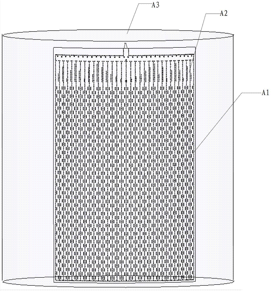
[0036] Embodiment 1 discloses a waveguide slot antenna, such as figure 1 shown, including: waveguide slots
[0037] Array A1, feed network A2 and metal cylinder A3.
[0038] A plurality of substrate-integrated waveguide slot subarrays A1 based on the H-plane Taylor distribution, the waveguide slot sub-arrays A1 constitute the ultra-low sidelobe pattern on the H-plane of the waveguide slot antenna;
[0039] One or a plurality of feeding networks A2 connected to the waveguide slot sub-array A1 are used to respectively feed signals of unequal power and different phases to the connected waveguide slot sub-array A1 to control the waveguide slot sub-array A1 The slot antenna E-plane array forms an E-plane Taylor distribution array used to form an E-plane ultra-low sidelobe pattern;
[0040] The metal cylinder A3, the waveguide slot sub-array A1 and the feeding network A2 are connected around the circumference of the metal cylinder A3.
[0041] It can be seen from the above techni...
Embodiment 2
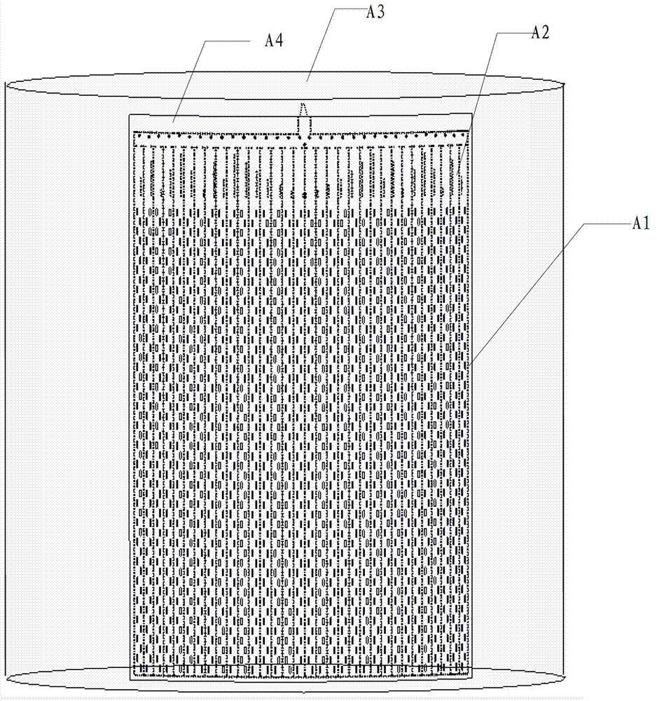
[0043] On the basis of Embodiment 1, this embodiment also discloses a waveguide slot antenna, such as figure 2 As shown, it includes: a waveguide slot sub-array A1, a feed network A2, a metal cylinder A3 and a dielectric substrate A4.
[0044] A plurality of substrate-integrated waveguide slot subarrays A1 based on the H-plane Taylor distribution, the waveguide slot sub-arrays A1 constitute the ultra-low sidelobe pattern on the H-plane of the waveguide slot antenna;
[0045] One or a plurality of feeding networks A2 connected to the waveguide slot sub-array A1 are used to respectively feed signals of unequal power and different phases to the connected waveguide slot sub-array A1 to control the waveguide slot sub-array A1 The slot antenna E-plane array forms an E-plane Taylor distribution array used to form an E-plane ultra-low sidelobe pattern;
[0046] The metal cylinder A3, the waveguide slot sub-array A1 and the feeding network A2 are connected around the circumference of...
Embodiment 3
[0050] On the basis of the second embodiment, this embodiment also discloses a waveguide slot antenna, including: a waveguide slot sub-array A1, a feeding network A2, a metal cylinder A3 and a dielectric substrate A4.
[0051] A plurality of substrate-integrated waveguide slot subarrays A1 based on the H-plane Taylor distribution, the waveguide slot sub-arrays A1 constitute the ultra-low sidelobe pattern on the H-plane of the waveguide slot antenna;
[0052] One or a plurality of feeding networks A2 connected to the waveguide slot sub-array A1 are used to respectively feed signals of unequal power and different phases to the connected waveguide slot sub-array A1 to control the waveguide slot sub-array A1 The slot antenna E-plane array forms an E-plane Taylor distribution array used to form an E-plane ultra-low sidelobe pattern;
[0053] The metal cylinder A3, the waveguide slot sub-array A1 and the feeding network A2 are connected around the circumference of the metal cylinder...
PUM
 Abstract
Description
Claims
Application Information
 - R&D
- Intellectual Property
- Life Sciences
- Materials
- Tech Scout
- Unparalleled Data Quality
- Higher Quality Content
- 60% Fewer Hallucinations
Browse by: Latest US Patents, China's latest patents, Technical Efficacy Thesaurus, Application Domain, Technology Topic, Popular Technical Reports.
© 2025 PatSnap. All rights reserved.Legal|Privacy policy|Modern Slavery Act Transparency Statement|Sitemap|About US| Contact US: help@patsnap.com


