
Capacitive touch screen and manufacturing method thereof

The technology of a capacitive touch screen and a manufacturing method, which is applied to the input/output process of electrical digital data processing, instruments, and data processing, etc., can solve the problems of grinding, high production cost, long cycle, etc., and achieve beautiful and unified line connection, Reasonable structure design and short production cycle

Active Publication Date: 2012-12-12
GANZHOU DPT TECH
View PDF4 Cites 11 Cited by
  • Summary
  • Abstract
  • Description
  • Claims
  • Application Information

AI Technical Summary

Problems solved by technology

The GFF structure is a layer of glass laminated with two layers of conductive film. Since this structure is equipped with two layers of conductive film, two layers of adhesive are required to achieve the bonding of the three. The overall thickness is usually more than 0.55mm, and the touch effect is not good. ;The GG structure is formed by laminating two layers of glass. In this structure, the thickness of the lower layer of glass is usually 0.55mm. If the upper layer of glass is 0.55mm, the strength is not enough, and if 0.70mm is used, the total thickness will be too thick, which will affect the touch effect. ;The PG structure is that the upper layer of PET is bonded to the lower layer of glass. In this structure, the lower layer of glass cannot be cut into special shapes or opened holes, and the surface hardness of the upper layer of PET is only 3H. As a protective cover, the hardness is not enough and it is easy to scratch. Grinding, etc.; OGS is monolithic glass touch, which prints all the circuits on the glass cover, and has made a great breakthrough in thickness, but because it needs to use yellow light process when making circuits, the production cost is high And the cycle is long. At the same time, because the flexible circuit board is directly bonded to the glass cover and there is no protective layer on the lower surface, there is a hidden danger of peeling off the bonding position.

Method used


Image

  • Capacitive touch screen and manufacturing method thereof
  • Capacitive touch screen and manufacturing method thereof
  • Capacitive touch screen and manufacturing method thereof

Examples


Embodiment Construction

[0034] It should be noted that, in the case of no conflict, the embodiments in the present application and the features in the embodiments can be combined with each other. The present invention will be further described in detail below in conjunction with the drawings and specific embodiments.

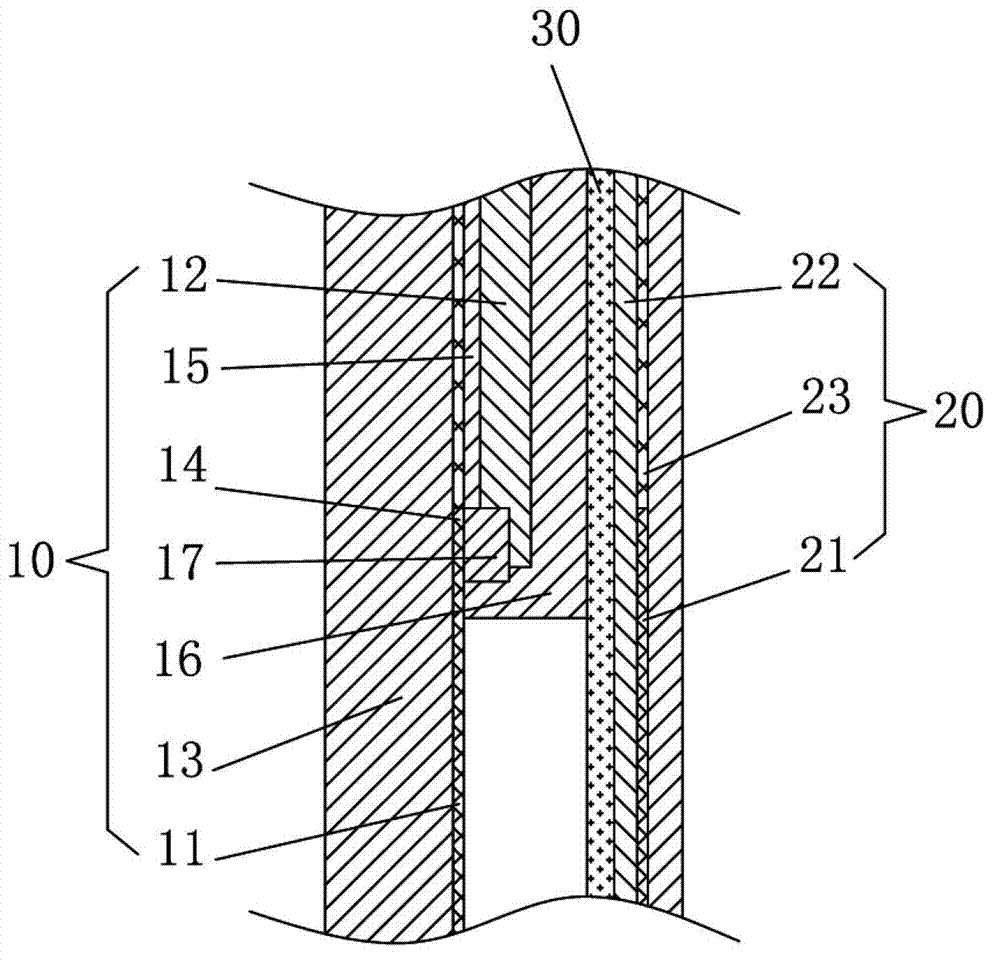
[0035] Such as Figure 1~Figure 4 As shown, the embodiment of the present invention provides a capacitive touch screen (Glass-1 Film, G1F for short), which includes a touch base layer 10 and a touch sensing layer 20 attached to the touch base layer 10 .

[0036] As we all know, touch screens are generally divided into a touch area and a non-touch area. The touch area is the operation window, which is used to control the device to operate according to the specified command through finger touch operation. The non-touch area is the window frame. On the periphery of the operation window, it is used to protect and hide the circuit, and can better beautify the operation window. The capaciti...


PUM


Abstract

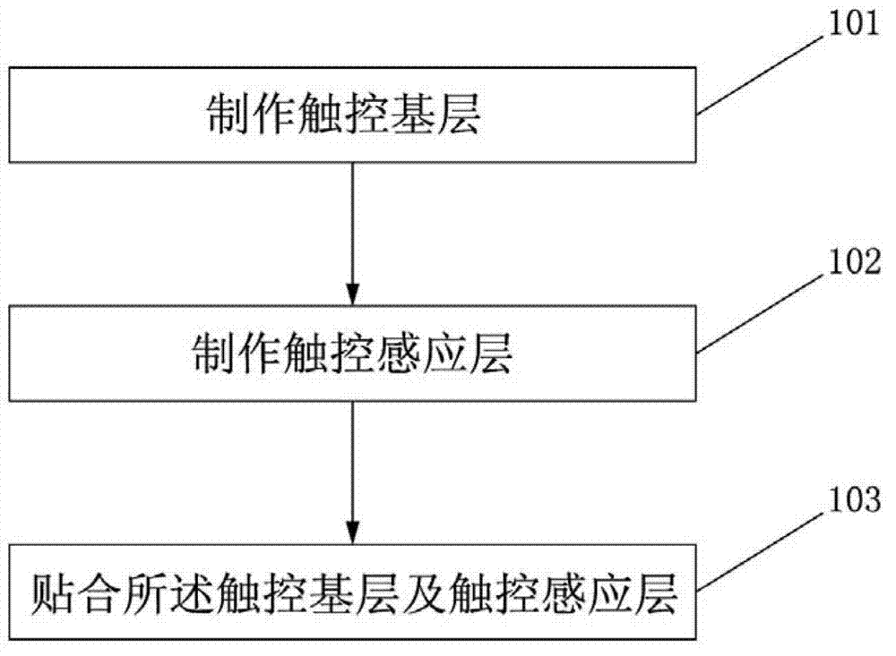
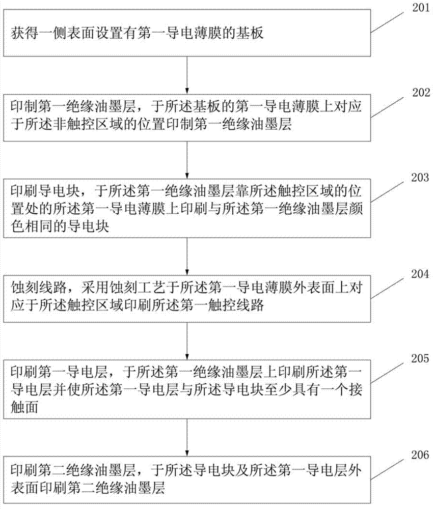
The embodiment of the invention discloses a capacitive touch screen. The capacitive touch screen is respectively provided with a touch zone and a non-touch zone and comprises a touch basic layer and a touch sensing layer which is adhered to a first side surface of the touch basic layer by virtue of an adhesive layer. The embodiment of the invention also discloses a manufacturing method of the capacitive touch screen. The manufacturing method comprises the following steps of manufacturing the touch basic layer, manufacturing the touch sensing layer and bonding. According to the capacitive touch screen disclosed by the embodiment of the invention, through the arrangement of the touch basic layer and the touch sensing layer, the bonding of the touch basic layer and the touch sensing layer is realized by adopting optical cement, the structure is reasonable, the thickness is appropriate, the manufacturing technology is simple, and the cost is low.

Description

technical field [0001] The invention relates to the technical field of touch screens, in particular to a capacitive touch screen and a manufacturing method thereof. Background technique [0002] With the rapid development of science and technology, touch technology, as the most simple, convenient and natural way of human-computer interaction, has received global attention and has been widely used in various industries. With the increasing popularity of touch screens in electronic products, it has now dominated the market. Existing touch screens of electronic products can be divided into four types: resistive, capacitive, infrared and surface acoustic wave according to their working principles and transmission information media. Control and other advantages are highly sought after. [0003] A capacitive touch screen is a touch screen that senses touch signals through the combination of electrodes and human body characteristics. When the four sides of the touch screen are p...

Claims


Application Information

Patent Timeline
Patent Type & Authority Applications(China)
IPC IPC(8): G06F3/044
Inventor 张恒军廉政汤灵平周姗姗梁爱军
Owner GANZHOU DPT TECH
Learn More