
Numerical control gear hobbing machine hob spindle mechanism

A gear hobbing machine and spindle technology, which is applied in the field of gear processing machine tools, can solve the problems of relatively high rigidity and speed requirements of the spindle, failure to satisfy automation, and complex structure, and achieve the requirements of automatic production, simple structure, and reduced production costs. Effect

Inactive Publication Date: 2012-12-12
浙江陀曼智能科技股份有限公司
View PDF5 Cites 6 Cited by
  • Summary
  • Abstract
  • Description
  • Claims
  • Application Information

AI Technical Summary

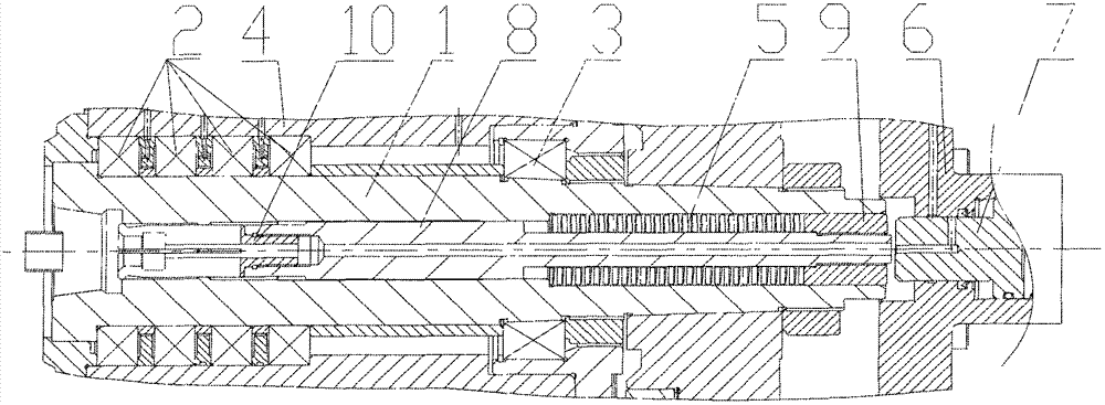
Problems solved by technology

[0002] At present, gear hobbing machines generally use spiral hobs to process gears according to the generation method, and hobs generally cut gears intermittently. The tool spindle mechanism is generally complex in structure, high in cost, poor in rigidity, and low in speed, which cannot well meet the needs of automation

Method used


Image

  • Numerical control gear hobbing machine hob spindle mechanism
  • Numerical control gear hobbing machine hob spindle mechanism

Examples


Embodiment Construction

[0010] Specific embodiments of the present invention will be described in detail below in conjunction with the accompanying drawings.

[0011] The mechanism has an oil mist lubrication interface, an operating gas circuit interface and an operating oil circuit interface.

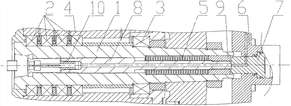
[0012] Such as Figure 1-2 The present invention shown includes: the pull claw 10 is fixed on the pull rod 8, the nut 9 locks the rear end of the mold spring 5 sleeved on the pull rod 8 and can adjust the spring pressure, and the front end of the mold spring 5 is stuck on the shoulder of the inner hole of the main shaft 1 The main shaft 1 is fixed on the main shaft box 4 through the angular contact bearing 2 of the front journal and the double-row cylindrical roller bearing 3 of the rear journal, and the piston 7 at the rear end of the main shaft 1 is connected to the cylinder housing 6 . There is an oil mist lubrication channel on the spindle box 4, the pull rod 8 and the pull claw 10 are hollow structures,...


PUM


Abstract

The invention relates to a gear cutting machine, in particular to a numerical control gear hobbing machine hob spindle mechanism. An oil mist lubricating port, an operation gas circuit port and an operation oil circuit port are arranged on the mechanism. A pull claw, a pull rod, a mold spring and a nut are all arranged in a spindle. An angular contact bearing is arranged at a front shaft neck of the spindle, and a double-line cylindrical roller bearing is arranged at a rear shaft neck. An operation oil cylinder at the rear end of the spindle is fixed on a spindle box. The numerical control gear hobbing machine hob spindle mechanism has the advantages that a spindle rear bearing is the double-line cylindrical roller bearing and is good in rigidity; a spindle bearing adopts an oil mist lubrication method which enables the spindle bearing to be fully lubricated so as to increase rotary speed of the spindle; the center of the spindle blows gas and can blow a locating conical hole on the front portion of the spindle cleanly so as to guarantee repeated installing precision of a hob; and the mold spring is used for locking the pull claw, installing is convenient, and cost is low.

Description

technical field [0001] The invention relates to a gear processing machine tool, in particular to a hob spindle mechanism of a gear hobbing machine. Background technique [0002] At present, gear hobbing machines generally use spiral hobs to process gears according to the generation method, and hobs generally cut gears intermittently. The tool spindle mechanism generally has a complex structure, high cost, poor rigidity, and low speed, which cannot well meet the needs of automation. Contents of the invention [0003] The purpose of the present invention is to solve the above-mentioned shortcomings of the existing hob spindle, and provide a hob high rigidity spindle mechanism with simple structure, compact and reasonable, convenient installation, and capable of withstanding intermittent cutting. For this reason, the present invention adopts following technical scheme: [0004] A hob spindle mechanism for gear hobbing machines, characterized in that the claws are fixed on t...

Claims


Application Information

Patent Timeline
Patent Type & Authority Applications(China)
IPC IPC(8): B23B19/02
Inventor 刘罡陶富强周国君吕潮斌
Owner 浙江陀曼智能科技股份有限公司
Learn More