
A method for correcting count rate drift in a quantum-counting detector and an x-ray system

A technology of counting detectors and detectors, applied in X-ray energy spectrum distribution measurement, instruments, measuring devices, etc., can solve problems such as difficulty in accurately determining dose, image error, counting rate drift, etc.

Active Publication Date: 2012-12-05
SIEMENS HEALTHCARE GMBH
View PDF4 Cites 12 Cited by
  • Summary
  • Abstract
  • Description
  • Claims
  • Application Information

AI Technical Summary

Problems solved by technology

In these quantum counting detectors, the high X-ray photon flux in clinical CT scanners leads to the build-up of space charges in the typically used CdTe / CdZnTe detector materials, which can lead to significant count rate drift
This count rate drift makes precise dose determination difficult and generally leads to image errors and, in CT systems, especially noticeable artifacts in tomographic images created from absorption data

Method used


Image

  • A method for correcting count rate drift in a quantum-counting detector and an x-ray system
  • A method for correcting count rate drift in a quantum-counting detector and an x-ray system
  • A method for correcting count rate drift in a quantum-counting detector and an x-ray system

Examples


Embodiment Construction

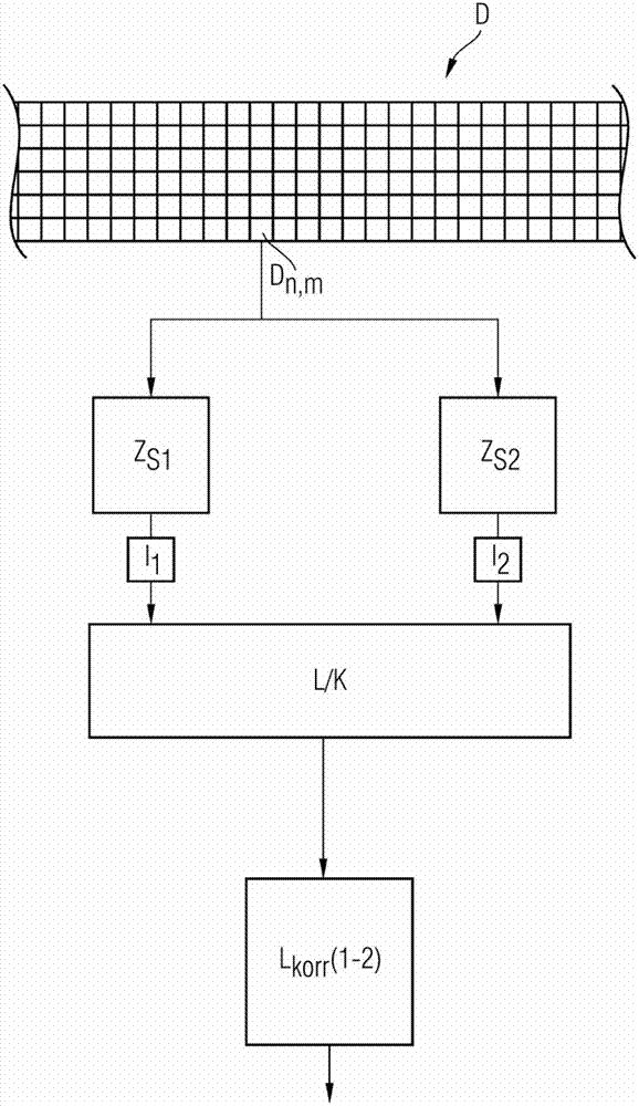
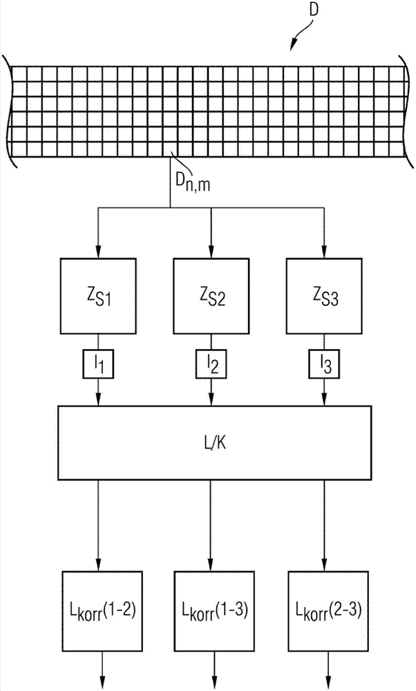
[0057] figure 1 shows a detector element with quantum counting D n,m A schematic cross-sectional view of a detector D with not fully shown detector electronics. In the detector electronics of the detector element, the electrical signal from the detector element D n,m transferred in parallel to two counters Z S1 and Z S2 , wherein the counters are adjusted with different thresholds S1 and S2 (e.g. 20keV and 60keV) corresponding to their subscripts, so as to count only electrical signals corresponding to at least 20keV or at least 60keV incident on the detector element Gamma quantum. from counter Z S1 and Z S2 will count the pulse rate I 1 and I 2 to the logic and correction unit L / K, where the drift correction according to the invention of the measured count rate is based on the found value at the count rate I 1 with I 2 The relation between is corrected, and as the corrected logarithmic pulse rate L korr (1-2) output.

[0058] exist figure 2 A variant of a detect...


PUM


Abstract

The invention relates to a method, a circuit arrangement and an X-ray system, in particular a CT system (1), are disclosed wherein, in order to correct the count rate drift of a detector for ionizing radiation having quantum-counting detector elements (Dn, m) which include a combination of at least two counters (ZS1, ZS2, ZS3) with significantly different energy thresholds (S1, S2, S3), and on the basis of previously determined functional dependencies of count rates on one another and using at least one of the counters (ZS1, ZS2, ZS3) per detector element as the reference, the count rates of the respective other counters with different energy thresholds are corrected.

Description

technical field [0001] The invention relates to a method for correcting count rate drift in detectors of X-ray systems, in particular CT systems, with quantum counting detector elements, each detector element having at least A combination of two counters, the energy threshold is analyzed in combination for determining the incident radiation dose. Furthermore, the invention relates to an x-ray system with a quantum counting detector and a circuit arrangement of the quantum counting detector. Background technique [0002] X-ray systems with quantum counting detectors, in particular CT systems, and methods for analyzing detector pulses from the detectors are generally known. For application in CT systems in recent years, besides conventional detector types with integrating detector elements used hitherto, such quantum counting detectors have been suggested as possible solutions for reducing patient dose and for Measured energy-resolved in a single-source CT system. In these ...

Claims


Application Information

Patent Timeline
IPC IPC(8): G01T1/29A61B6/03
CPCG01T1/40A61B6/583A61B6/032A61B6/037
Inventor S.卡普勒
Owner SIEMENS HEALTHCARE GMBH
Learn More