Eureka AIR delivers breakthrough ideas for toughest innovation challenges, trusted by R&D personnel around the world.

Sensing/detecting device capable of reflecting internal force change and internal displacement of rock-soil

A detection device and internal force technology, applied in the direction of measuring devices, electric devices, measuring force, etc., can solve the problems of inability to predict and prevent, manual detection, and inability to detect internal force changes, etc., and achieve low loss, simple structure, and application high value effect

Inactive Publication Date: 2012-12-05
莫也兰
View PDF7 Cites 15 Cited by
  • Summary
  • Abstract
  • Description
  • Claims
  • Application Information

AI Technical Summary

Problems solved by technology

[0003] Chinese patent 201010195972.2 "Debris flow and landslide detection device based on omnidirectional tilt sensor and omnidirectional visual sensor" provides a debris flow and landslide detection device, which solves the problem of manual detection of debris flow and landslides in the past
Although this method detects the displacement of rock and soil, because it only detects the displacement of the surface, it cannot detect the change of internal force, nor can it achieve the purpose of prediction and prevention.

Method used


Image

  • Sensing/detecting device capable of reflecting internal force change and internal displacement of rock-soil
  • Sensing/detecting device capable of reflecting internal force change and internal displacement of rock-soil
  • Sensing/detecting device capable of reflecting internal force change and internal displacement of rock-soil

Examples


Embodiment Construction

[0024] The accompanying drawings show specific embodiments of the present invention.

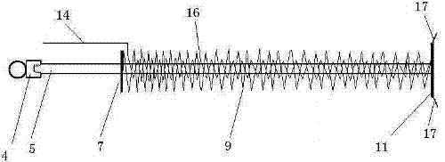
[0025] The detection device is composed of an inductor 3, two induction rods 1-1, 1-2 and two stay ropes 2-1, 2-2. Connecting bolt 4 is a cylinder with a ring, which connects the sliding bar and the stay rope of the sensor, and the connecting bolt with the sliding bar is realized by the ring on the connecting bolt with the connection of the stay cord. When in use, bury the sensing rod in the slope soil or rock to be detected.

[0026] The inductor 3 is a key part of the present invention, and is composed of a sliding rod assembly, an external sleeve and an internal resistance coil.

[0027] The outer sleeve is cylindrical, used to fix and install the sliding rod device, the internal resistance coil, and transmit the displacement relationship at one end of the sensing rod. The inner resistance coil is tightly attached to the fixed sleeve 8 of the outer sleeve. The front part of the outer s...


PUM


Abstract

The invention discloses a sensing / detecting device capable of reflecting an internal force change and internal displacement of rock-soil. The sensing / detecting device comprises a sensor, sensing rods and pulling ropes, wherein two ends of the sensor are respectively connected with one end of each pulling rope; the other ends of the pulling ropes are connected with the sensing rods; and two sensing rods are fixed into the rock-soil; the sensor is composed of a sliding rod assembly, an outer sleeve and an inner resistance wire ring; the sliding rod assembly and the inner resistance wire ring are installed inside a sleeve; one end of a sliding rod is connected with a sliding rod connecting bolt; the other end of the sliding rod is fixed on a spring support ring on the rear end of the sliding rod; a stressed spring is sleeved on the sliding rod; a sliding brush is installed on the spring support ring on the rear end of the sliding rod and is contacted and communicated with resistance wires; stress changes of the sensing rods are transmitted to the sensor, then a displacement change is generated at a position where the sliding brush is contacted with the resistance wires, output leads of the resistance wires and a output lead of the sliding brush are changed in length, resistance is changed, therefore, a change of the the rock-soil is obtained by measuring the resistance between the output leads of the resistor wires and the output lead of the sliding brush. The sensing / detecting device is simple in structure, low in cost, high in reliability and convenient and practical.

Description

(1) Technical field [0001] The invention relates to a monitoring device for geological disasters, in particular to a sensing detection device capable of reflecting changes in rock and soil internal force and internal displacement. (two), background technology [0002] In our country, there are vast areas of mountains and hills, and roads are generally built along the mountains. This has just caused many natural disasters caused by landslides. The occurrence of geological disasters such as side slopes and tunnel collapses will cause huge property losses every year, and even endanger life safety. [0003] Chinese patent 201010195972.2 "Debris flow and landslide detection device based on omnidirectional tilt sensor and omnidirectional visual sensor" provides a debris flow and landslide detection device, which solves the problem of manual detection of debris flow and landslides in the past. However, this detection device has a complex structure, high cost, and cannot detect in...

Claims


Application Information

Patent Timeline
Patent Type & Authority Applications(China)
IPC IPC(8): G01L1/22G01B7/02
Inventor 莫也兰
Owner 莫也兰
Why Eureka
Eureka Blog
Learn More