
Small multiband polarization imaging system with automatic filter wheel

A polarization imaging and optical filter technology, which is applied in the field of multi-band polarization imaging systems, can solve the problem of only obtaining polarization images of specific bands, and achieve the effects of saving manpower and financial resources, small size, and improving detection capabilities

Inactive Publication Date: 2014-08-20
NORTHWESTERN POLYTECHNICAL UNIV
View PDF6 Cites 0 Cited by
  • Summary
  • Abstract
  • Description
  • Claims
  • Application Information

AI Technical Summary

Problems solved by technology

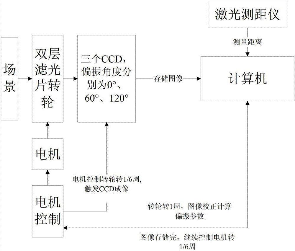
[0004] In order to avoid the deficiencies of the existing technology, the present invention proposes a small automatic filter wheel multi-band polarization imaging system, which overcomes the defect that the existing detection means can only obtain the radiation intensity of the target surface or only obtain the polarization image of a specific band

Method used


Image

  • Small multiband polarization imaging system with automatic filter wheel
  • Small multiband polarization imaging system with automatic filter wheel
  • Small multiband polarization imaging system with automatic filter wheel

Examples


Embodiment Construction

[0025] Now in conjunction with embodiment, accompanying drawing, the present invention will be further described:

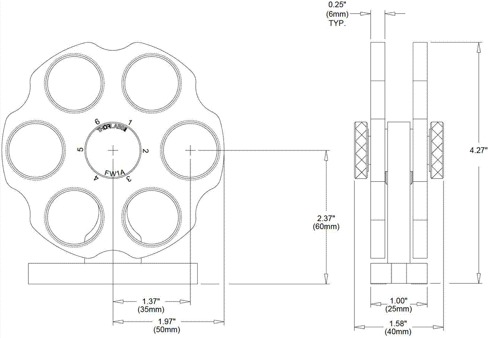
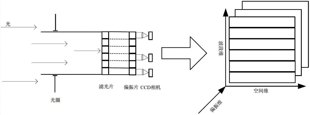
[0026] Such as figure 1 As shown, the system includes filter wheels, three CCD cameras, motors, laser range finders, circuit control units and other parts. Such as figure 2 As shown, the filter wheel is located at the front end of the system, allowing only specific wavelength bands of white light to pass through; followed by the polarizer in front of the camera lens, and the transmission axis and reference direction of the three polarizers are fixed at 0° , 60°, 120°. Put a CCD camera behind each polarizer for imaging. In this plan, 5 filters and 1 neutral filter are selected. The central wavelength and bandwidth of the 5 filters are 400nm, 10nm; 450nm, 10nm; 550nm , 40nm; 650nm, 10nm; 700nm, 10nm. The structure of the wheel is shown in the figure. Filters are mounted in the individual holes of the wheel. In this example, the CCD camera is Vis MV-1300, and...


PUM


Abstract

The invention relates to a small multiband polarization imaging system with an automatic filter wheel. The small multiband polarization imaging system is characterized by comprising the double-layer filter wheel, three charge coupled device (CCD) cameras, a motor system, a laser range finder and a computer, wherein polarizing films are arranged at the fronts of the three CCD cameras; the double-layer filter wheel is arranged between the polarizing films and a shot scene and is controlled by the motor system; the three CCD cameras output a shot image to the computer to be processed; the laser range finder outputs measured distance signals to the computer; the computer geometrically corrects the image and computes parameters of the polarized image according to information of the laser range finder, and after polarization multiband is acquired, the computer transmits signals to the motor system so as to control rotation of the double-layer filter wheel. The image is quickly acquired by controlling rotation of the motor, and the system also has functions of image preprocessing, storage and communication, so that purposes of stably and reliably working and saving labor and financial resources can be achieved.

Description

technical field [0001] The invention relates to a multi-band polarization imaging system, in particular to a novel optomechanical-electrical integrated multi-band polarization imaging system, which integrates a circuit control unit hardware module for data acquisition and processing. Background technique [0002] In the prior art, prototypes of imaging polarization spectrometers have appeared at home and abroad, but there are still certain defects and deficiencies in application. For example, the National Aerospace Laboratory of Japan adopts the technology of rotating polarized electric tuning filter to obtain polarization spectrum images, but there are problems such as poor reliability of the imaging system, poor accuracy of image acquisition, and inability to obtain real polarization information of the same instantaneous target. The polarization component image of the same band is obtained instantaneously, so the real polarization spectrum information of the target cannot ...

Claims


Application Information

Patent Timeline
Patent Type & Authority Patents(China)
IPC IPC(8): G01J3/447G01J4/04
Inventor 赵永强张清勇杨劲翔
Owner NORTHWESTERN POLYTECHNICAL UNIV
Learn More