
High-speed waterspout inertia-ejection cylinder

A projectile cylinder and water column technology, which is applied to liquid spray guns, weapons without explosives, offensive equipment, etc., can solve the problems of damage to the spray shape of the water column in the projectile cylinder and inability to spray, and achieve the effect of easy reuse and prevention of leakage.

Inactive Publication Date: 2012-12-05
GENERAL ENG RES INST CHINA ACAD OF ENG PHYSICS
View PDF4 Cites 0 Cited by
  • Summary
  • Abstract
  • Description
  • Claims
  • Application Information

AI Technical Summary

Problems solved by technology

In the process of inertial ejection of the water column of the existing water column projecting cylinder, due to the integrated structure or fixed connection between the cylinder seat and the upper cylinder body, when the water column starts to project, a negative pressure will be formed at the bottom of the projecting cylinder, and the negative pressure will It will lead to the destruction of the shape of the water column in the projectile cylinder during the spraying process, and it will not even be able to be sprayed out in the form of a water column

Method used


Image

  • High-speed waterspout inertia-ejection cylinder
  • High-speed waterspout inertia-ejection cylinder

Examples


Embodiment Construction

[0021] The present invention will be further described below in conjunction with accompanying drawing:

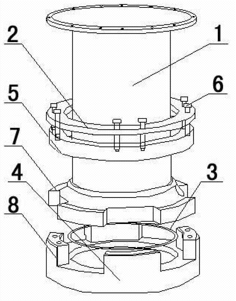
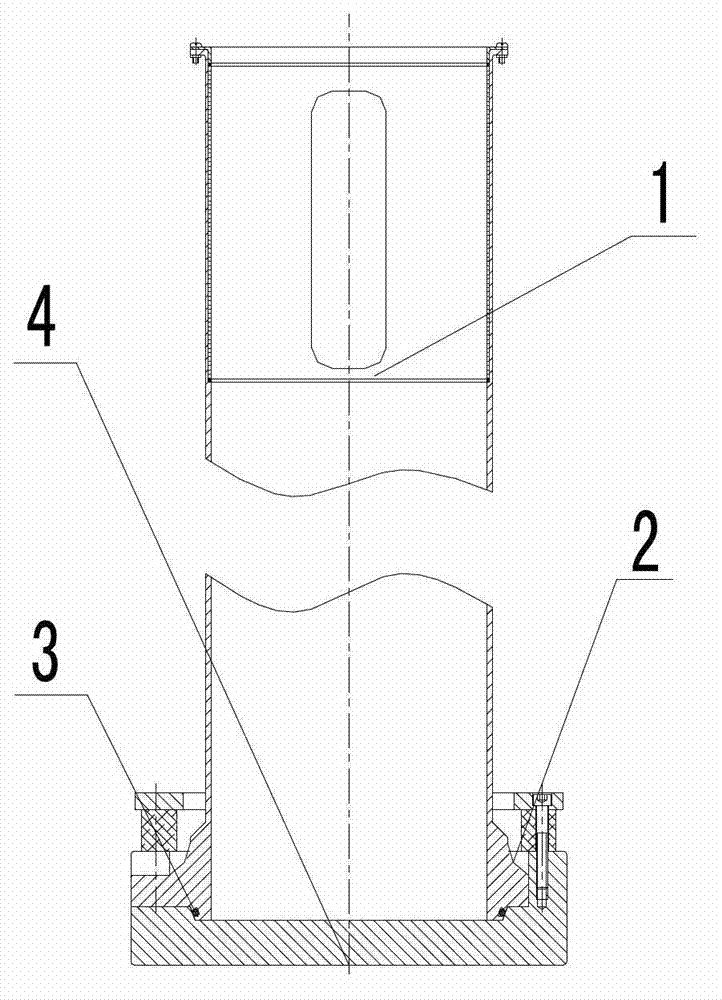
[0022] Such as figure 1 with figure 2 As shown: the present invention includes an upper cylinder body 1, a cylinder seat 4 and a limit ring. The upper edge of the cylinder seat 4 is evenly distributed with a plurality of cylinder seat protrusions 8 protruding upwards. Between adjacent cylinder seat protrusions 8 Grooves are formed, and the lower end edge of the upper cylinder 1 is evenly distributed with a plurality of upper cylinder bumps 7 protruding outward. In the groove, the thickness of the protrusion 7 of the upper cylinder is 8cm smaller than the height of the protrusion 8 of the cylinder seat. The limit ring includes the rubber ring 5 at the lower end and the limit steel ring 2 at the upper end. The limit ring is set on the upper cylinder 1 outside.

[0023] Such as figure 1 with figure 2 As shown: the limit ring is connected with the cylinder seat bump 8 th...


PUM


Abstract

The invention discloses a high-speed waterspout inertia-ejection cylinder comprising an upper cylinder body, a cylinder seat and a limit ring. Cylinder seat bumps protruding upwards are uniformly distributed at the edge of the upper end of the cylinder seat, and a groove is formed between each two adjacent cylinder seat bumps. Upper cylinder bumps protruding outwards are uniformly distributed at the edge of the lower end of the upper cylinder and are arranged in the grooves. The thickness of each upper cylinder bump is smaller than the height of each cylinder seat bump. The limit ring is sleeved outside the upper cylinder. The upper cylinder and the cylinder seat are in separable structure, in the process of ejecting waterspout out of the ejection cylinder, the bottom of the ejection cylinder is communicated with the atmosphere, negative pressure at the bottom of the ejection cylinder is eliminated, and accordingly, ejection of regular waterspouts is realized.

Description

technical field [0001] The invention relates to a water column projecting tube, in particular to a high-speed water column inertial projecting tube. Background technique [0002] With the development and use of various hard buffer materials (such as rubber, hard aluminum, etc.) Various loading platforms etc. The projectile cylinder drives the projectile to stop suddenly after obtaining a certain initial velocity, and the projectile is launched under the action of inertia. In the process of inertial ejection of the water column of the existing water column projecting cylinder, due to the integrated structure or fixed connection between the cylinder seat and the upper cylinder body, when the water column starts to project, a negative pressure will be formed at the bottom of the projecting cylinder. It will lead to the destruction of the shape during the spraying of the water column in the projectile cylinder, and it will not even be able to be sprayed out in the form of a wa...

Claims


Application Information

Patent Timeline
IPC IPC(8): F41B9/00
Inventor 李思忠王小龙莫军刘显军卢永刚李明海郝志明刘伟周本权
Owner GENERAL ENG RES INST CHINA ACAD OF ENG PHYSICS
Learn More