Variable-focus light emitting device

A light-emitting device and variable technology, which are applied to lighting devices, fixed lighting devices, components of lighting devices, etc., can solve the problem of large-accommodating space lens groups, difficult to miniaturize or thin design, and difficult to follow the user's needs. It is necessary to adjust the angle of the lighting direction and other issues to achieve the effect of changing the lighting range and changing the lighting angle.

Inactive Publication Date: 2012-12-05
BENQ CORP
View PDF5 Cites 6 Cited by
  • Summary
  • Abstract
  • Description
  • Claims
  • Application Information

AI Technical Summary

Problems solved by technology

Generally, the way to change the illumination range is usually to achieve optical zoom by combining multiple lenses. By adjusting the relative position between the lens groups, different illumination ranges are produced. However, this method of using lens groups for optical zoom requires more Large accommodation space for the mutual movement of mechanism components and lens groups, making it difficult to achieve miniaturization or thinning design
In addition, since the structural elements and lens groups are configured on the light-emitting device, usually the illumination range of the light-emitting surface of the light-emitting device can only be changed by optical zoom, and it is difficult to adjust the angle of the lighting direction according to the user's needs. Demanding lighting devices, such as active turn lights, require more rotatable mechanism components, controllers and motors, and use motors to drive rotatable mechanism components to rotate the lens group to change the angle. These additional components make the entire lighting device Larger accommodation space is required, so it is not easy to achieve miniaturization or thinning of optical devices that can change the illumination range and illumination angle at the same time

Method used


Image

  • Variable-focus light emitting device
  • Variable-focus light emitting device
  • Variable-focus light emitting device

Examples


no. 1 example

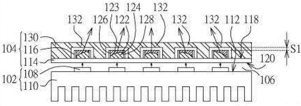
[0033] Figure 1A is a cross-sectional view of the variable-focus light emitting device according to the first embodiment. The variable-focus lighting device includes a light source module 102 and a zoom module 104 . The zoom module 104 is disposed on one side of the light source module 102 . For example, the space 106 between the light source module 102 and the zoom module 104 can be air or other fluids with different refractive indices.

[0034] Please refer to Figure 1A , the light source module 102 includes a plurality of semiconductor light emitting units 108 . The semiconductor light emitting unit 108 can be disposed on the first surface 112 of the plate heat sink 110 to quickly and efficiently dissipate the heat energy dissipated from the semiconductor light emitting unit 108 and improve the service life of the semiconductor light emitting unit 108 . The semiconductor light emitting unit 108 may include a light emitting diode (LED), a laser diode (LD), or an organic ...

no. 2 example

[0046] Figure 5 It is a cross-sectional view of the variable-focus light emitting device in the second embodiment. The difference between the second embodiment and the first embodiment is that the transparent material structure 232 of the solid transparent material layer 230 has a lens structure, for example, the lens structure is a convex lens structure or a concave lens structure. In this embodiment, the transparent material structure 232 is a spherical concave lens structure. In other embodiments, the transparent material structure 232 of the solid transparent material layer 230 may be a convex lens structure (not shown in the figure), such as a spherical convex lens. The light emitted from the liquid lens 116 enters the transparent material structure 232 having a lens structure, and then is emitted after being refracted by the transparent material structure 232 . Using the transparent material structure 232 with an optically designed lens structure can change the output...

no. 3 example

[0048] Figure 6 It is a cross-sectional view of the variable-focus light emitting device in the third embodiment. The difference between the third embodiment and the second embodiment is that the transparent material structure 332 of the solid transparent material layer 330 is an aspheric concave lens structure. In other embodiments, for example, the transparent material structure 332 of the solid transparent material layer 330 may be an aspheric convex lens structure (not shown in the figure).


PUM


Abstract

The invention provides a variable-focus light emitting device which comprises a light source module and a focus varying module. The light source module comprises a plurality of semiconductor light emitting units. The focus varying module is disposed on one side of the light source module and comprises a circuit board and a plurality of liquid lenses disposed on the circuit board. The liquid lenses comprise first liquid and second liquid. A liquid interface is disposed between the first liquid and the second liquid. The liquid lenses correspond to the light emitting units. Different curvature of the liquid interface is generated by the liquid lenses according to different voltage applied by the circuit board. Light emitted by the light emitting units irradiates into corresponding liquid lenses, and angles of the light emitting from the liquid lenses changes according to the curvature of the liquid interface. By the variable-focus light emitting device, lighting range and light angles can be changed, and size miniaturization and thinning of the overall device are facilitated.

Description

technical field [0001] The invention relates to a light emitting device, in particular to a variable focus light emitting device. Background technique [0002] Lighting devices are very common in daily life, especially lighting devices that can change the lighting range, such as stage lights, display lights, car lights, warning lights or fish collection lights and so on. Generally, the way to change the illumination range is usually to achieve optical zoom by combining multiple lenses. By adjusting the relative position between the lens groups, different illumination ranges are produced. However, this method of using lens groups for optical zoom requires more The large accommodation space allows the mechanism components and the lens group to move with each other, and it is not easy to achieve miniaturization or thinning design. In addition, since the structural elements and lens groups are configured on the light-emitting device, usually the illumination range of the light-...

Claims


Application Information

Patent Timeline
Patent Type & Authority Applications(China)
IPC IPC(8): F21S8/00G02B3/14F21V23/00F21Y101/02
Inventor 李孝文
Owner BENQ CORP
Why Eureka
Try Eureka