A fixture for chamfering the end of a steel pipe

A chamfering and fixture technology, which is applied in the direction of manufacturing tools, metal processing equipment, metal processing machinery parts, etc., can solve the problems of inconvenient, inconvenient adjustment of the tool and fixture center, high chamfering rejection rate, etc., to achieve convenient chamfering processing , Stable tightening and simple fixture structure

Inactive Publication Date: 2015-10-14
WUHU TONHE AUTOMOBILE FLUID SYST
View PDF6 Cites 0 Cited by
  • Summary
  • Abstract
  • Description
  • Claims
  • Application Information

AI Technical Summary

Problems solved by technology

But the shortcoming of the fixture for chamfering processing in the prior art is that it is not convenient, stable, mechanized, and multi-purpose to realize the chamfering processing work of multiple pipe diameters (the center adjustment of the cutter and the fixture is very inconvenient, resulting in waste products of chamfering high rate)

Method used


Image

  • A fixture for chamfering the end of a steel pipe
  • A fixture for chamfering the end of a steel pipe
  • A fixture for chamfering the end of a steel pipe

Examples


Embodiment Construction

[0021] Below with reference to the accompanying drawings, through the description of the embodiments, the specific embodiments of the present invention, such as the shape, structure, mutual position and connection relationship between the various parts, the role and working principle of the various parts, etc., will be further described. Detailed instructions:

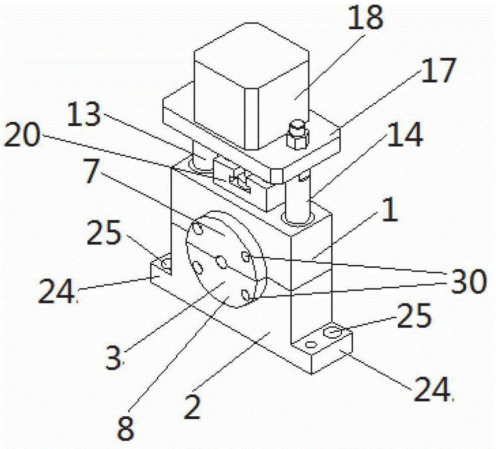
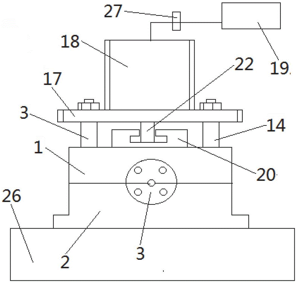
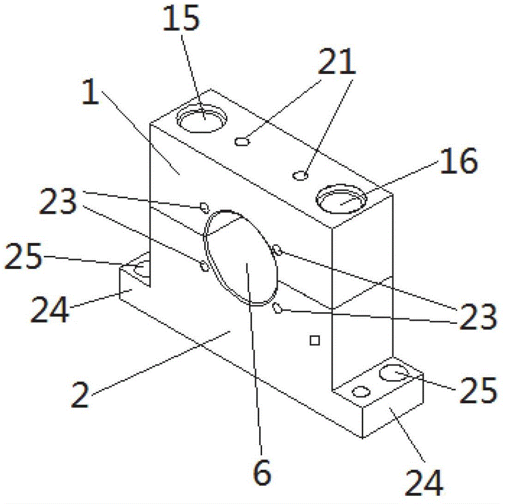
[0022] as attached figure 1 — attached Figure 5 As shown, the present invention is a fixture for chamfering the end of a steel pipe. The fixture includes an upper mold base 1, a lower mold base 2, and a clamping mold 3. After the upper mold base 1 and the lower mold base 2 are fastened and connected, The concave part I4 on the upper mold base 1 and the concave part II5 on the lower mold base 2 form the mold hole 6 that penetrates the upper mold base 1 and the lower mold base 2, and the upper body part 7 and the lower body part 8 of the clamping die 3 are set to be able to The structure connected with the upper mold ...


PUM


Abstract

The invention provides a fixture for chamfering ends of steel pipes, and is applied to the technical field of machining of steel pipes. A concave portion I (4) of an upper die holder (1) and a concave portion II (5) on a lower die holder (2) of the fixture for chamfering the ends of the steel pipes form a die hole (6), an upper body (7) and a lower body (8) of a clamp die (3) are respectively connected with the upper die holder (1) and the lower die holder (2), an upper pipe diameter portion (9) of the upper body (7) and a lower pipe diameter portion (10) of the lower body (8) are fastened to form a cylindrical pipe diameter portion (11), and the pipe diameter portion (11) penetrates through the die hole (6) and is of a structure capable of accommodating a steel pipe (12) in a sleeved manner. The fixture can clamp the steel pipes, so that the ends of the steel pipes can be chamfered conveniently. In addition, the fixture is simple in structure, and only clamp dies comprising pipe diameter portions with different sizes need to be changed before the steel pipes with different pipe diameters are machined.

Description

technical field [0001] The invention belongs to the technical field of steel pipe processing, and more specifically relates to a clamp for chamfering the end of a steel pipe. Background technique [0002] With the continuous development of the automobile industry, the pursuit of higher quality in all aspects of the automobile, especially the piping, will more directly affect the life and safety of the automobile. Therefore, the details of the steel pipes have become more stringent. In order to The ends of steel pipes with different pipe diameters are chamfered conveniently, stably and quickly. In the prior art, there have been fixtures for chamfering processing of steel pipes with multiple pipe diameters. But the shortcoming of the fixture for chamfering processing in the prior art is that it is not convenient, stable, mechanized, and multi-purpose to realize the chamfering processing work of multiple pipe diameters (the center adjustment of the cutter and the fixture is ver...

Claims


Application Information

Patent Timeline
Patent Type & Authority Patents(China)
IPC IPC(8): B23Q3/00
Inventor 滕传祥
Owner WUHU TONHE AUTOMOBILE FLUID SYST
Why Eureka
Try Eureka