
Repairing method for connecting rod for reeling machine jaw

A repair method and connecting rod technology, applied in the direction of adopting mechanical devices, mechanical measuring devices, mechanical gap measurement, etc., can solve problems such as increased gap between jaws, deformation of fan-shaped plates, long cycle, etc.

Inactive Publication Date: 2012-12-05
武钢集团有限公司
View PDF6 Cites 4 Cited by
  • Summary
  • Abstract
  • Description
  • Claims
  • Application Information

AI Technical Summary

Problems solved by technology

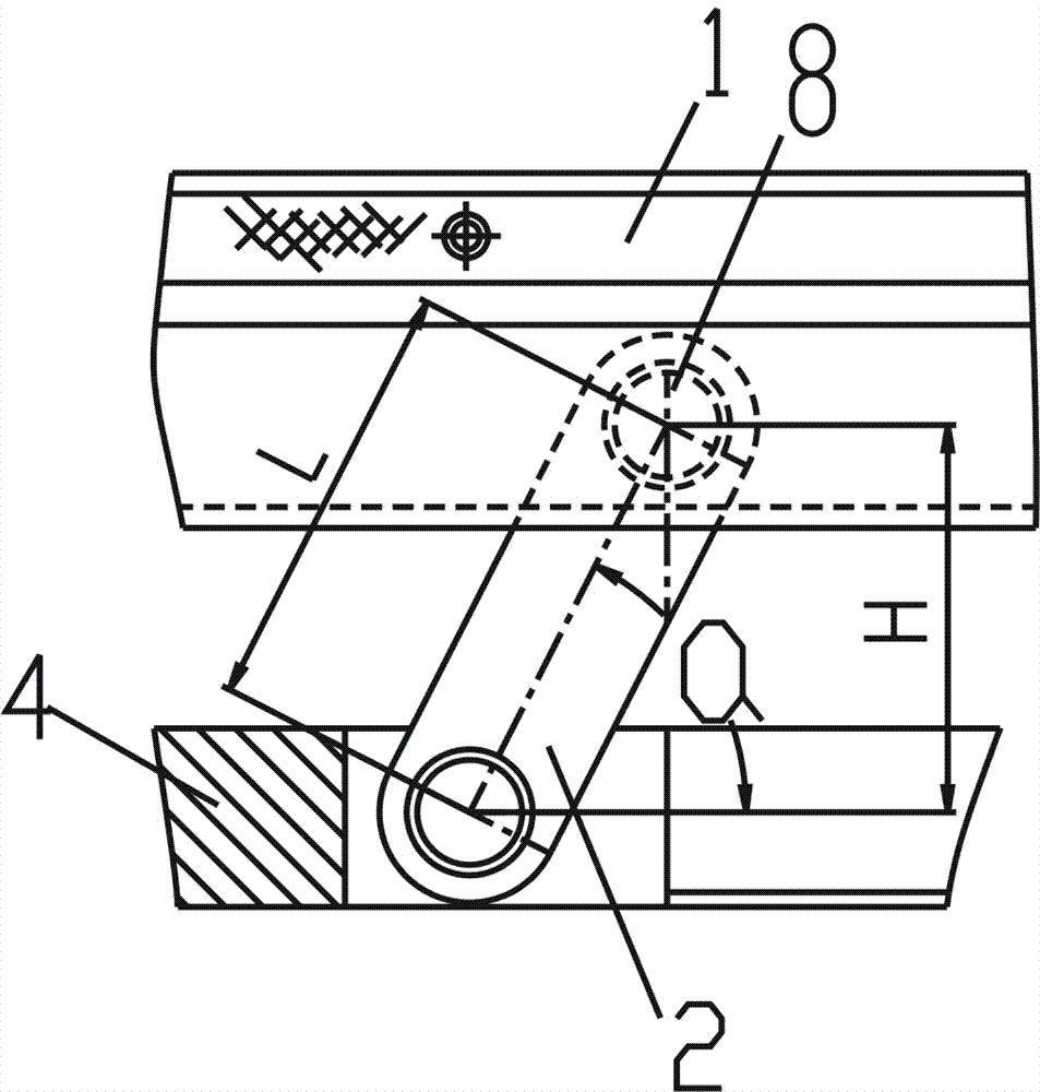
However, in actual production, due to improper operation, untimely maintenance or long running time, the connecting rod will be worn, the gap between the jaws will increase, and the clamping of the steel plate will be weak. In order to meet the rounding requirements, the connecting rod extension angle α will continue to increase ( There is a surplus value in the cylinder stroke), once the amount of wear accumulates to the limit value so that L≤90mm, then α≥90°, which will cause the on-site connecting rod to overturn and get off the machine
[0005] The previous repair plan was: repair or replace each part of the jaw mechanism one by one, including large-area repair welding processing of fan-shaped plates, pyramids, upper pull bars, new copper sleeves, pin shafts and connecting rods, etc., repeated repair welding Processing and thermal stress accumulation can easily cause deformation of the fan-shaped plate and affect the life of spare parts, and the entire repair cost is high and the cycle is long, which cannot meet user requirements

Method used

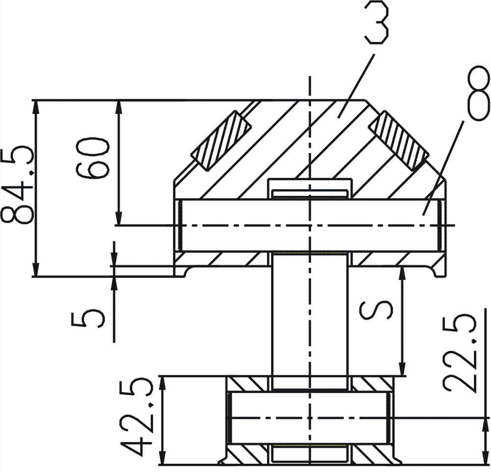
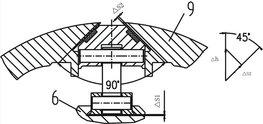

Image

  • Repairing method for connecting rod for reeling machine jaw
  • Repairing method for connecting rod for reeling machine jaw
  • Repairing method for connecting rod for reeling machine jaw

Examples


Embodiment Construction

[0022] The present invention will be further described below in conjunction with the accompanying drawings.

[0023] as attached figure 1 As shown, it is a schematic diagram of the assembly of the reel of the coiler, from the attached figure 1 It can be seen from the figure that the coiler reel includes a mandrel 7, on the outside of the mandrel 7 there are pyramidal shaft 6, fan-shaped plate 5 and jaw fan-shaped plate 9, above the mandrel is the jaw part of the coiler, the jaw The part is hinged in the form of a pin 8 by the connecting rod 2, the upper jaw brace 3 and the lower dovetail brace 4 on the inner side of the jaw iron 1, and the head of the steel plate is clamped and coiled under the compression of the spring force.

[0024] The key of the method of the present invention is the measurement of the connecting rod and the accurate conversion of the error. According to the difference in the wear and tear of the field use, the calculation formula increases and decreases...


PUM


Abstract

The invention discloses a repairing method for a connecting rod for a reeling machine jaw. The vertical distance actually required between two pin holes is obtained by measurement and calculation; the vertical distance actually required between the two pin holes is divided by a sin value of the maximum stretch corner of the connecting rod, so that the actual length of the connecting rod to be repaired is obtained; and a connecting rod meeting the length requirement is selected to replace the connecting rod according to the actual length of the connecting rod to be repaired, thereby accomplishing the repairing of the connecting rod for the reeling machine jaw. With the adoption of the method, the wearing of each part is not required to be analyzed and modified, only gaps at the head and tail of a whole worn chain is required to be controlled and eliminated, the connecting rod is lengthened or shortened for compensation, and other worn parts such as copper bushes and pin shafts are still repaired according to the designed dimensions. The method is simple and practical, complicated detailed analysis is avoided, and the practice proves that the repairing quality of a reeling machine can be ensured completely, and the field use requirements can be met.

Description

technical field [0001] The invention relates to a device repair method, in particular to a repair method for jaw connecting rods in coilers of metallurgical steel rolling equipment. Background technique [0002] The coiler is a representative equipment for coiling steel plates or strips into coils in the metallurgical industry. According to different uses and structures, it has many types. The hot-rolled leveling line uses a coiler with tension reel, which is a hydraulic detachable wedge type. The fan-shaped plate and the pyramid shaft are matched with a slope of 1:5, and the oil cylinder is connected to the mandrel for reciprocating motion. When the mandrel drives the pyramid shaft to move to the right, the effect of the slope makes the reel open, and vice versa makes the reel shrink. [0003] For ease of explanation, see the attached figure 1 , from attached figure 1 It can be seen from the figure that the reel of the coiler includes a mandrel. On the outside of the man...

Claims


Application Information

Patent Timeline
Patent Type & Authority Applications(China)
IPC IPC(8): B23P6/00G01B5/02G01B5/14
Inventor 蔡岚玲徐国华李家志章述涛苏碧辉
Owner 武钢集团有限公司
Learn More