
Pulse laser distance measurement method for parallel counting by multiple counters and handheld pulse laser distance measurer applying method

A technology of pulse laser ranging and laser ranging, which is applied in the direction of instruments, measuring devices, and using re-radiation, can solve the problems that the rangefinder cannot perform distance measurement, limits the range of the rangefinder, and the error of the ranging result.

Inactive Publication Date: 2012-11-28
付陆欣 +1
View PDF9 Cites 4 Cited by
  • Summary
  • Abstract
  • Description
  • Claims
  • Application Information

AI Technical Summary

Problems solved by technology

[0003] It can be seen that if the threshold voltage is selected too low, before the echo signal returns, the noise signal higher than the threshold voltage will form a false echo signal through the voltage comparator, resulting in an error in the ranging result
And when the threshold voltage is increased, the noise signal is lower than the threshold voltage to suppress the noise, but an excessively high threshold voltage will make the weaker echo signal unable to pass through
Under the same conditions (including environment, optical system, receiving amplification system, etc.), as the distance increases, the signal received by the receiving system will also decrease. After reaching a certain distance, the rangefinder will not be able to measure the distance. This greatly limits the measuring range of the rangefinder.

Method used


Image

  • Pulse laser distance measurement method for parallel counting by multiple counters and handheld pulse laser distance measurer applying method
  • Pulse laser distance measurement method for parallel counting by multiple counters and handheld pulse laser distance measurer applying method

Examples


Embodiment Construction

[0025] The present invention will be further described below in conjunction with the accompanying drawings.

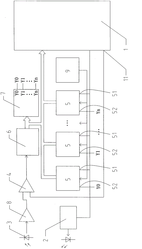
[0026] The invention provides a multi-counter parallel counting pulse laser ranging method, its schematic diagram can be referred to figure 2 As shown, the method includes the following steps:

[0027] (a), the ranging controller (commonly known as MCU) emits the first ranging pulse, and at the same time starts several high-speed counters connected and controlled by the ranging controller, and the high-speed counter starts counting and is used to record the sent ranging pulse to the ranging control The duration of the echo signal received by the device, during which the ranging controller is commonly used in the existing hand-held pulse laser rangefinder, and it can use the traditional control MCU.

[0028] (b), compare the echo signal received by the distance measurement with the threshold voltage set by the voltage comparator, the setting of the threshold voltage c...


PUM


Abstract

The invention discloses a pulse laser distance measurement method for parallel counting by multiple counters. A target distance is constant, so that a counted value of reflection pulses is constant; however, interference pulses are random, so that a counted value corresponding to each interference pulse is completely different; and after frequent measurement is performed, an accurate value of a measured target can be obtained through mathematical statistic analysis. By the method, the interference pulses can be effectively eliminated, and threshold voltage of echo signals can be reduced, so that the requirement on the strength of the echo signals is reduced, the measured distance is increased, and the distance measurement accuracy is improved. The invention also discloses a handheld pulse laser distance measurer applying the method. The handheld pulse laser distance measurer is manufactured based on the distance measurement method; the measured target is subjected to frequent emission pulse distance measurement, and the accurate value of the measured target can be obtained through the mathematical statistic analysis. The distance measurer can reduce the threshold voltage of the echo signal, the measured distance can be increased, and the distance measurement accuracy is improved.

Description

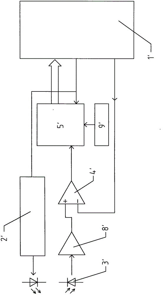
technical field [0001] The present invention relates to the field of hand-held pulse laser ranging technology and the hand-held pulse laser range finder applying the technology, specifically a multi-counter parallel counting pulse laser ranging method and the hand-held pulse laser ranging applying the method instrument. Background technique [0002] attached figure 1 Shown is the block diagram of the traditional hand-held pulse laser rangefinder circuit structure. Its ranging method and structure are as follows: when starting ranging, the ranging controller 1' (commonly known as MCU) sends a ranging pulse through the laser tube driving circuit 2', and the laser tube driving circuit 2' emits laser pulses at the same time Also start the high-speed counter 5' to start counting. The clock signal input end of the high-speed counter 5' is connected to an oscillator 9'. When the emitted laser pulse irradiates the measured target, it is reflected back and enters the photoelectric ...

Claims


Application Information

Patent Timeline
IPC IPC(8): G01S17/08
Inventor 付陆欣李春富
Owner 付陆欣
Learn More