Eureka AIR delivers breakthrough ideas for toughest innovation challenges, trusted by R&D personnel around the world.

Method for measuring motion parameters of target in linear array image

A technology of motion parameters and linear array images, applied in the fields of image processing and photogrammetry, can solve problems such as high algorithm requirements, difficult to guarantee accuracy, and large amount of data, and achieve the effect of clear target outline, accurate measurement, and high resolution

Inactive Publication Date: 2012-11-28
NAT UNIV OF DEFENSE TECH
View PDF7 Cites 6 Cited by
  • Summary
  • Abstract
  • Description
  • Claims
  • Application Information

AI Technical Summary

Problems solved by technology

These two methods are based on the optical images acquired by the area array camera. The first method needs to process a large amount of data. Due to the limitation of the shooting frequency of the area array camera, in order to obtain the sequence image of the target, it is often necessary to set up multiple The camera is used for shooting, which increases the difficulty of camera calibration and layout
The second method needs to obtain the motion displacement of the target from the motion blur of the target, which has high requirements for the algorithm of feature extraction, and the accuracy is difficult to guarantee
At present, there is no research on the measurement method in this area

Method used


Image

  • Method for measuring motion parameters of target in linear array image
  • Method for measuring motion parameters of target in linear array image
  • Method for measuring motion parameters of target in linear array image

Examples


Embodiment Construction

[0017] The present invention will be described in detail below in conjunction with the accompanying drawings.

[0018] The first step is to calibrate the line scan camera.

[0019] What adopted in the present invention is the line array camera as the tool of photogrammetry. The imaging model of the line-scan camera includes the inner and outer orientation elements of the line-scan camera, and these azimuth elements are obtained through the calibration of the line-scan camera. For the calibration of the line-scan camera and the description of the imaging model, see: C.A.Luna, M.Mazo, et al, Calibration of Line-Scan Cameras, IEEE TRANSACTIONS ON INSTRUMENTATION AND MEASUREMENT, 2010, 59, (8), pp.2185- 2190.

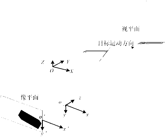
[0020] In order to describe the time-space relationship of line scan camera imaging, the following coordinate system is defined (as attached figure 2 shown):

[0021] Measurement coordinate system O-XYZ: In the measurement of the actual moving target, select any point ...


PUM


Abstract

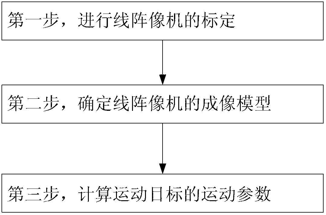
The invention provides a method for measuring motion parameters of a target by using optical images. The technical scheme is as follows: the method comprises the following steps of: (1) calibrating a linear array camera: acquiring inner azimuth elements and outer azimuth elements of the linear array camera; (2) determining an imaging model of the linear array camera: determining an imaging geometrical relationship between any point in a space and a corresponding imaged point of the point; and (3) calculating the motion parameters of a moving target: selecting at least five characteristic points from the moving target, obtaining a nonlinear equation on the motion parameters of the target by using the imaging geometrical relationship between the characteristic points and corresponding imaged points of the characteristic points, and obtaining the motion parameters of the target through equation solving. According to the method provided by the invention, the motion parameters of the moving target can be accurately measured.

Description

technical field [0001] The invention relates to the fields of photogrammetry and image processing, in particular to a method for measuring object motion parameters in line array images. Background technique [0002] The motion analysis and parameter measurement of targets in optical images are widely used in national defense early warning, traffic control and other fields, and have long been an important subject of long-term research in the fields of photogrammetry and image processing. In the detection, tracking and recognition of various moving objects, the measurement of moving parameters is a key content. [0003] At present, there are two main methods of measuring the motion parameters of the target using optical images: the first method is to continuously shoot the target to obtain the sequence images of the target motion, and calculate the distance of the target motion by calculating the distance of the target motion between adjacent image frames. Parameters such as ...

Claims


Application Information

Patent Timeline
Patent Type & Authority Applications(China)
IPC IPC(8): G01C11/00
Inventor 文贡坚赵竹新回丙伟
Owner NAT UNIV OF DEFENSE TECH
Why Eureka
Eureka Blog
Learn More