
Glue pot of glue spraying type thread-free glue binding machine

A wireless glue binding machine and glue-spraying technology, which is applied in binding adhesives, book binding, printing, etc., can solve the problems of hot-melt adhesive bonding performance degradation, difficult control of glue temperature, and pollution of the working environment. Easy to achieve glue temperature, short melting time and good bonding performance

Active Publication Date: 2014-08-13
浙江大祥办公设备有限公司
View PDF7 Cites 0 Cited by
  • Summary
  • Abstract
  • Description
  • Claims
  • Application Information

AI Technical Summary

Problems solved by technology

[0003] The existing traditional hot-melt adhesive binding technology has made a qualitative leap compared with the original manual glue binding, which greatly improves the quality of book binding. However, this traditional hot-melt adhesive binding still has the following insurmountable defects: 1. Due to the opening of the glue tank, the hot melt adhesive in the glue tank keeps volatilizing, which not only wastes the glue liquid, but also pollutes the working environment; 2. The hot melt adhesive in the glue tank has repeatedly experienced heating, cooling, and carbonization The process is always regenerated glue, repeated use, the bonding performance of the hot melt adhesive will be greatly reduced; 3. Every time the machine is turned on and used, the solidified hot melt adhesive must be melted before sizing, and the melting time is long. And the glue temperature is not easy to control

Method used


Image

  • Glue pot of glue spraying type thread-free glue binding machine
  • Glue pot of glue spraying type thread-free glue binding machine
  • Glue pot of glue spraying type thread-free glue binding machine

Examples


Embodiment Construction

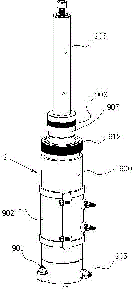
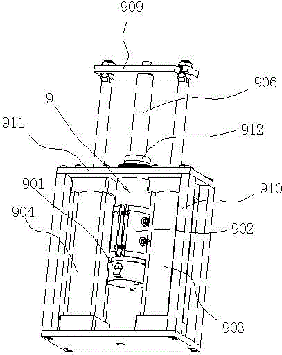
[0031] Such as Figures 1 to 9As shown, a glue tank of a glue-spraying wireless glue filling machine, the glue tank 9 includes a vertically arranged cylindrical glue chamber 900, the bottom of the glue chamber 900 is sealed, and the inside of the glue chamber 900 is sealed. A pressure piston 906 that can slide up and down is provided. The pressure piston 906 includes a piston head 907 located at the end of the pressure rod 906. The middle part of the piston head 907 is provided with an annular piston push piece 908. The ring piston push piece 908 The material is tetrafluoroethylene, the other end of the pressure rod 906 is connected with the piston rods of the left and right cylinders 904, 903 arranged on both sides of the glue tank 9 through a cross brace 909, and the tops of the left and right cylinders 904, 903 It is fixed on the inside of the top plate 911 of the frame 910 by bolts, and the glue tank 9 is fixed on the inside of the top plate 911 by the glue tank locking ri...


PUM


Abstract

The invention discloses a glue pot of a glue spraying type thread-free glue binding machine. The glue pot comprises a cylindrical glue cavity which is vertically arranged, wherein the bottom end of the glue cavity is sealed, a pressure piston which can slide up and down is arranged in the cavity of the glue cavity, a glue outlet is arranged at the bottom of the glue cavity, the glue cavity is provided with a melt glue heating part for melting melt glue contained in the cavity, and the glue outlet is connected with a glue inlet of a spray nozzle of the glue spraying type thread-free glue binding machine through a glue conveying pipe provided with a heating part for the glue conveying pipe on the periphery. The invention provides the glue pot of the glue spraying type thread-free glue binding machine, which can overcome the defects that the hot melt glue in the glue pot in the prior art is volatized continuously and further pollutes the working environment, as well as the defects that the hot melt glue in the glue pot is heated, cooled and carbonized repeatedly, thereby further preventing the reduction of the adhesive performance of the hot melt glue. Books or documents which are completely glue-bound can avoid the phenomena of page falling, cracking of book backs and the like, and two adjacent pages can be flattened by 180 degrees to facilitate reading, copying or scanning, thereby being another revolution in thread-free glue binding of the books or documents.

Description

technical field [0001] The invention relates to a wireless glue binding machine for books, in particular to a glue tank of a glue spraying type wireless glue binding machine. Background technique [0002] Existing wireless glue binding machines, such as Figure 10 As shown, it mainly includes a frame, a stack clamping mechanism 1 arranged on the frame, and a gap milling slot for the lower side of the stack 2 (also called the back) is provided at the front and lower side of the stack clamping mechanism 1. Milling cutter mechanism 3, in the front of said milling cutter mechanism 3, there is a sizing mechanism for coating the back glue on the lower side of the page stack 2 and coating side glue on both sides of the lower end of the page stack 2, a cover mechanism, and a As for the control device that controls the action of the above mechanism, the gluing mechanism includes a glue tank 4, a back rubber wheel 5 and a side rubber wheel 6. After the page stack clamping mechanism 1 ...

Claims


Application Information

Patent Timeline
Patent Type & Authority Patents(China)
IPC IPC(8): B42C9/00
Inventor 黄力树黄峥嵘
Owner 浙江大祥办公设备有限公司
Learn More