Loudspeaker testing device
A technology for testing devices and speakers, applied in the direction of electrical components, etc., can solve the problems that the sound quality of speakers cannot be guaranteed, reduce production efficiency, and consume
Active Publication Date: 2012-11-21
HUIZHOU JINSHAN ELECTRONICS
View PDF3 Cites 14 Cited by
- Summary
- Abstract
- Description
- Claims
- Application Information
AI Technical Summary
Problems solved by technology
The sound quality testing steps are separated from the production line, which not only reduces the production efficiency, but also consumes more manpower to participate in the handling of the speakers, which increases the production cost; the experience of the testers is used as the judgment standard for the sound quality of the speakers, resulting in the quality of the products. Unified control, the sound quality of the speaker cannot be guaranteed
Method used
View moreImage
Smart ImageViewing Examples
Examples
Embodiment 1
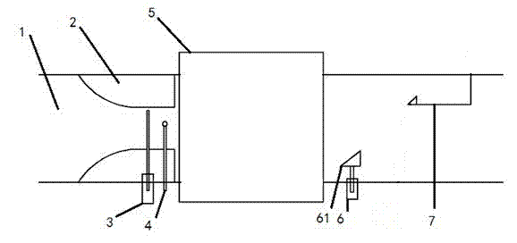
[0045] This embodiment discloses a horn testing device, which includes a stroke control mechanism for guiding and controlling the stroke of the horn to be tested from the upstream of the conveyor belt 1, and a testing mechanism arranged downstream of the stroke control mechanism and used for testing the horn to be tested.
Login to View More PUM
 Abstract
The invention relates to a loudspeaker testing device which comprises a travel control mechanism, a testing mechanism, a screening mechanism and a control mechanism, wherein the travel control mechanism is used for guide and travel control of to-be-tested loudspeakers coming from the upstream of a conveying belt; the testing mechanism is arranged on the downstream of the travel control mechanism and used for testing the to-be-tested loudspeakers; the screening mechanism is arranged on the downstream of the testing mechanism and used for screening qualified loudspeakers and defective loudspeakers; and the control mechanism is used for controlling the travel control mechanism, the testing mechanism and the screening mechanism. The loudspeaker testing device is high in production efficiency and capable of automatically performing online testing for the loudspeakers.
Description
technical field [0001] The invention relates to the technical field of horn testing equipment, in particular to a horn testing device. Background technique [0002] The speaker sound quality testing steps in the known speaker production process are all completed manually: the finished speaker products transmitted from the upstream of the production line are manually transferred to a quiet listening room, and the sound quality is tested based on the experience of the testers. The sound quality testing steps are separated from the production line, which not only reduces the production efficiency, but also consumes more manpower to participate in the handling of the speakers, which increases the production cost; the experience of the testers is used as the judgment standard for the sound quality of the speakers, resulting in the quality of the products. Unified control, the sound quality of the speaker cannot be guaranteed. Contents of the invention [0003] The object of th...
Claims
Login to View More Application Information
Patent Timeline
 IPC IPC(8): H04R29/00
Inventor 唐华吴洋梁志昌
Owner HUIZHOU JINSHAN ELECTRONICS
Features
- Generate Ideas
- Intellectual Property
- Life Sciences
- Materials
- Tech Scout
- Unparalleled Data Quality
- Higher Quality Content
- 60% Fewer Hallucinations
Learn More Browse by: Latest US Patents, China's latest patents, Technical Efficacy Thesaurus, Application Domain, Technology Topic, Popular Technical Reports.
© 2025 PatSnap. All rights reserved.Legal|Privacy policy|Modern Slavery Act Transparency Statement|Sitemap|About US| Contact US: help@patsnap.com

