


Quick Research
Generate reliable direction feasibility study reports for your R&D in just a few steps.

Technical Q&A
Discover and master advanced knowledge NOW. Basics, ideas, possibilities, all at once.

Find Solutions
As an expert in R&D theories, this can generate solutions to your technical problems instantly.

Evaluate Feasibility
Analyze your overall solution with one click, know your potential R&D risks in advance.

Monitor Landscape
Get weekly tech updates, stay abreast of the latest tech innovations and key insights.
Flag-shaped terminal with low inserting force and high extracting force
A technology of flag-shaped terminals and female terminals, which is applied in the field of terminal blocks and flag-shaped terminals, can solve the problems of stable connection with small insertion resistance, and achieve the effects of large elastic force, low insertion force, and wide range of action
- Summary
- Abstract
- Description
- Claims
- Application Information
AI Technical Summary
Problems solved by technology
Method used
Image

Examples
Embodiment 1
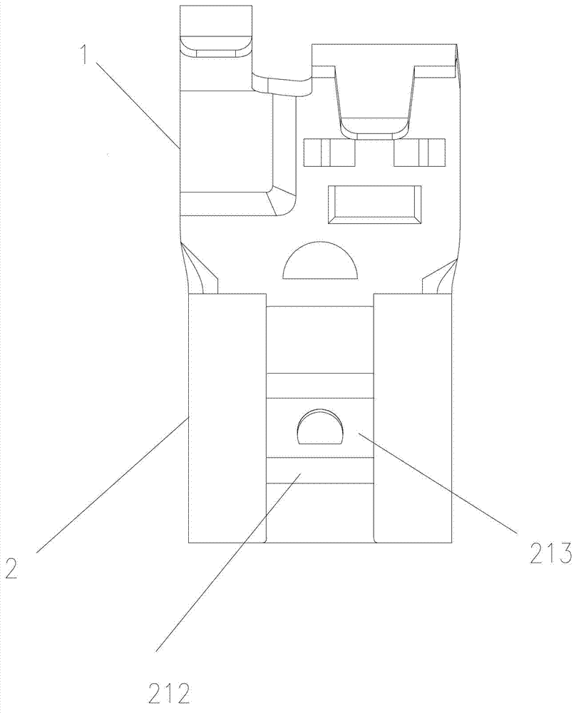
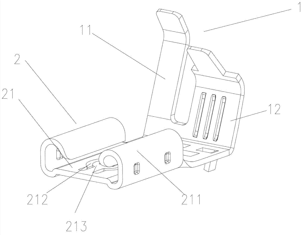
[0031] The structure of the flag-shaped terminal described in the present invention is shown in figure 2 As shown, it includes a cable connection part 1 and a wiring female terminal 2. The cable connecting part 1 is used for connecting cables, and generally includes a covering part 11 for wrapping the cable and a pressing part 12 for pressing the cable core. The female connection terminal 2 is used to connect a male connection terminal, such as a plug-in piece. In this embodiment, the connection direction of the cable connection part 1 is perpendicular to the connection direction of the connection female terminal 2 . The female terminal 2 includes a slot 21, the two sides of the slot 21 are arc-shaped tubular sidewalls 211, and the bottom of the slot 21 is formed with two longitudinal slits 212, such as figure 2 As shown, the width of the gap is set to 0.25mm. An elastic arm 213 is formed between the two slits 212, the length of the elastic arm 213 is 6mm, and the width i...
Embodiment 2
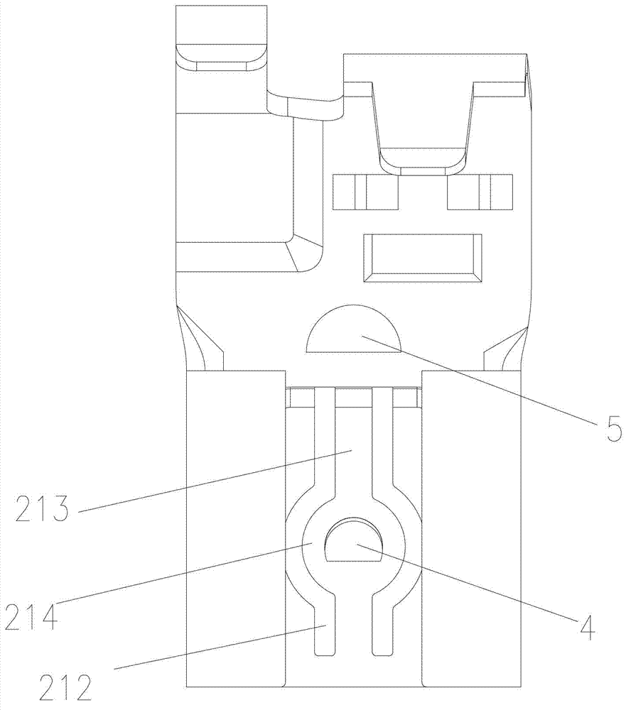
[0042] On the basis of the flag-shaped terminal described in Embodiment 1, a central extension 214 is further formed in the middle of the elastic arm 213, see image 3 , the width of the central expansion portion 214 is greater than the width of both ends of the elastic arm 213 . Here, the central expansion part 214 is circular and is disposed close to the notch of the slot 21 .
Embodiment 3
[0044] On the basis of the flag-shaped terminal described in the above embodiment, the inner wall of the arc-shaped tubular side wall 211 of the slot 21 is formed with a limited boss 3, see Figure 4 . The central expansion part 214 is provided with a locking protrusion 4, and the height of the locking protrusion 4 increases from one end close to the notch of the slot 21 to the other end, see image 3 .Such a structure has a smooth transition when inserting the male terminal, which is easy to insert, and has a groove structure when pulling out, so it is not easy to pull out, making the effect of low insertion force and high pull-out force more obvious. Further, at the bottom of the slot 21 and one end away from the notch of the slot 21, on the outer side of the elastic arm 213, a blocking protrusion 5 is provided, and the blocking protrusion 5 can limit the connection of the male terminal. depth, see image 3 .
PUM
| Property | Measurement | Unit |
|---|---|---|
| Length | aaaaa | aaaaa |
| Width | aaaaa | aaaaa |
| Length | aaaaa | aaaaa |
Abstract
Description
Claims
Application Information
 - R&D Engineer
- R&D Manager
- IP Professional
- Industry Leading Data Capabilities
- Powerful AI technology
- Patent DNA Extraction
Browse by: Latest US Patents, China's latest patents, Technical Efficacy Thesaurus, Application Domain, Technology Topic, Popular Technical Reports.
© 2024 PatSnap. All rights reserved.Legal|Privacy policy|Modern Slavery Act Transparency Statement|Sitemap|About US| Contact US: help@patsnap.com