
Automatic adjusting device of screw pair of single-screw pump

A screw and screw technology, applied in the field of automatic adjustment devices, can solve the problems of increased return flow, increased pressure drop, etc., and achieve the effects of reducing leakage, improving volumetric efficiency, and increasing pressure

Inactive Publication Date: 2012-11-21
重庆明珠机电有限公司
View PDF6 Cites 2 Cited by
  • Summary
  • Abstract
  • Description
  • Claims
  • Application Information

AI Technical Summary

Problems solved by technology

[0006] In addition, after the single-screw pump is used for a period of time, the gap between the screw and the stator will increase due to mutual friction, resulting in an increase in return flow and pressure drop, resulting in a decrease in volumetric efficiency
The current technology to solve this problem is manual adjustment, and the size of the adjustment amount and the time of adjustment cannot achieve the desired effect.

Method used


Image

  • Automatic adjusting device of screw pair of single-screw pump
  • Automatic adjusting device of screw pair of single-screw pump

Examples


Embodiment 1

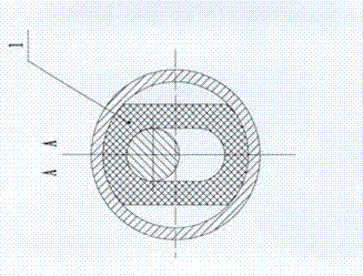
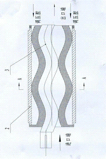
[0017] The screw pair includes a stator 1, a stator hoop 2 and a screw 3. The stator 1 is made of rubber; the stator hoop 2 is made of seamless steel pipe; the screw 3 is made of 45 steel. Stator 1 is a double-ended helical stator with equal wall thickness; its wall thickness is 5 mm. The stator 1 is fixed in the stator hoop 2 .

[0018] All the other technical features are the same as the technical solution.

Embodiment 2

[0020] The screw pair includes a stator 1, a stator hoop 2 and a screw 3. The stator 1 is made of rubber; the stator hoop 2 is made of seamless steel pipe; the screw 3 is made of 2Cr3. Stator 1 is a three-headed helical stator with equal wall thickness; its wall thickness is 10 mm. The stator 1 is fixed in the stator hoop 2 .

[0021] All the other technical features are the same as the technical solution.

Embodiment 3

[0023] The screw pair includes a stator 1, a stator hoop 2 and a screw 3. The stator 1 is made of rubber; the stator hoop 2 is made of seamless steel pipe; the screw 3 is made of 304 stainless steel. Stator 1 is a three-headed helical stator with equal wall thickness; its wall thickness is 20mm. The stator 1 is fixed in the stator hoop 2 .


PUM


Abstract

The invention relates to an automatic adjusting device of a screw pair of a single-screw pump. The automatic adjusting device comprises a stator 1, a stator steel hoop 2 and screws 3. The stator 1 is fixed into the stator steel hoop 2, and a pressure adjusting cavity extending along threaded helixes of the stator 1 and the stator steel hoop 2 is formed between the stator 1 and the stator steel hoop 2. The automatic adjusting device has the advantages that a gap of the screw pair can be adjusted automatically according to the pressure at an outlet end, pressure on the screw pair is increased, leakage is reduced, volumetric efficiency is enhanced, and 1.2MPa pressure can be generated by the one-level single screw pair.

Description

technical field [0001] The invention relates to an automatic adjustment device for a screw pair of a single screw pump. Background technique [0002] The screw meshes with the stator to create a seal line that forms a seal chamber to hold the medium. When the screw rotates in the specified anticlockwise direction, the volume of the sealed chamber moves to the outlet of the stator without changing, and the medium is delivered out. When the medium at the outlet is blocked, the pressure of the medium in the sealed cavity will increase accordingly. The seal chamber separated by the sealing line always has a pressure in the front (outlet side) greater than that in the rear direction. Therefore, only a small part of the medium squeezes out the sealing line and flows back to the rear, which reduces the delivery pressure and the delivery volume. This kind of leakage is inevitable, and the amount of backflow depends on the size of the sealing gap and the strength of the seal. If t...

Claims


Application Information

Patent Timeline
Patent Type & Authority Applications(China)
IPC IPC(8): F04C15/00F04C5/00
Inventor 易勇陈志民
Owner 重庆明珠机电有限公司
Learn More