
Contactless charging system

A non-contact charging and charging efficiency technology, applied in electromagnetic wave systems, charging stations, data exchange chargers, etc., can solve problems such as incomplete charging, and achieve the effect of preventing damage

Active Publication Date: 2015-05-06
HONDA MOTOR CO LTD
View PDF15 Cites 0 Cited by
  • Summary
  • Abstract
  • Description
  • Claims
  • Application Information

AI Technical Summary

Problems solved by technology

[0012] However, in the prior art described above, when it is determined that there is a magnetic foreign object on the primary coil, the operation of the power transmission transformer is stopped. Therefore, when the measured voltage exceeds a predetermined value due to the presence of a magnetic foreign object, for example, the target charging time The problem of not completing the charging

Method used


Image

  • Contactless charging system
  • Contactless charging system
  • Contactless charging system

Examples


Embodiment Construction

[0055] (non-contact charging system)

[0056] Embodiments of the present invention will be described based on the drawings.

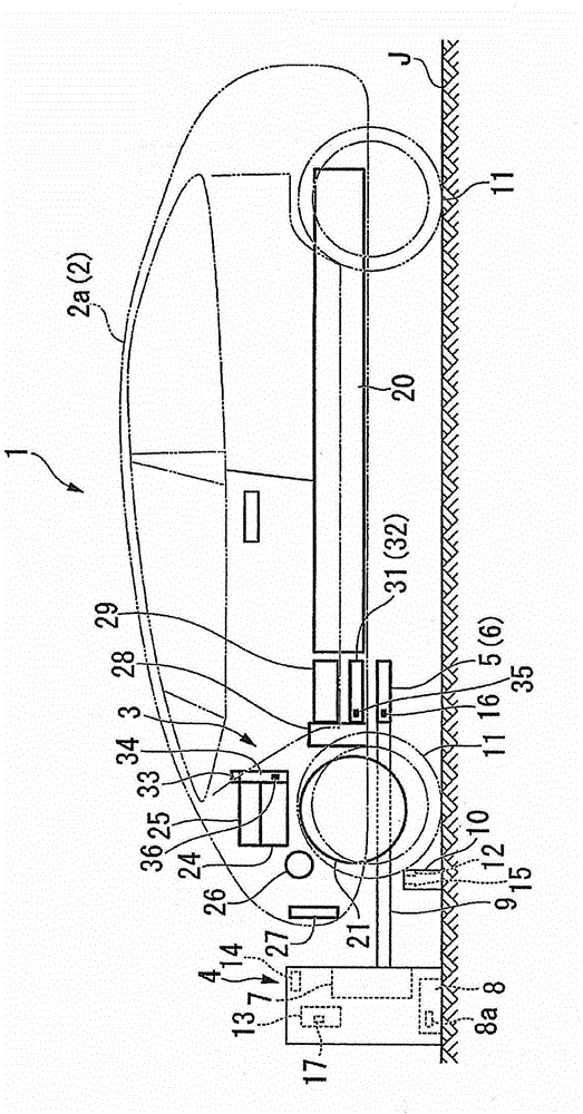
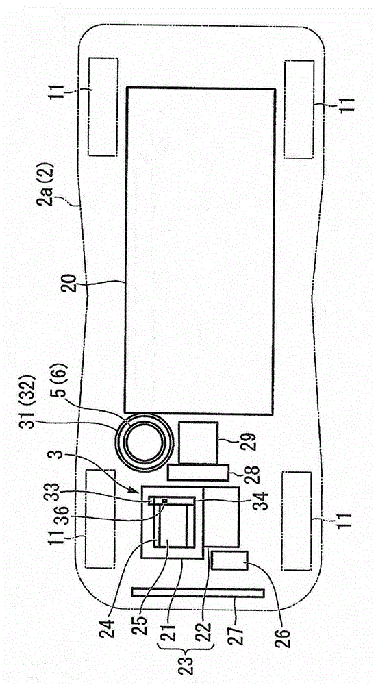
[0057] figure 1 It is a schematic diagram of the non-contact charging system 1 viewed from the side of the electric vehicle 2 . in addition, figure 2 It is a schematic diagram of the non-contact charging system 1 viewed from the upper side of the electric vehicle 2 . It should be noted that, in the following description, the forward direction of the electric vehicle 2 is referred to as the front, the backward direction is referred to as the rear, and the width direction of the electric vehicle 2 is referred to as the left-right direction. in addition, figure 2 in, omit figure 1 part of it.

[0058] Such as figure 1 and figure 2 As shown, the non-contact charging system 1 is, for example, a system for charging a battery 20 mounted on an electric vehicle 2 or the like. This non-contact charging system includes a vehicle-side charging device 3 ...


PUM


Abstract

A contactless charging system is provided with a transmitter having a primary coil which supplies power through electromagnetic induction, a receiver having a secondary coil which electromagnetically couples to the transmitter and receives power, and a controller which detects the charging efficiency from the primary coil to the secondary coil and varies the current supplied to the primary coil according to the charging efficiency.

Description

technical field [0001] The invention relates to contactless charging systems used eg in electric vehicles. [0002] This application claims priority based on Japanese Patent Application No. 2010-81401 for which it applied to Japan on March 31, 2010, The content is used here. Background technique [0003] For example, as a device for charging a battery mounted on an electric vehicle, a non-contact power transmission device (corresponding to the non-contact charging system in the present invention) is used. Such a non-contact power transmission device has a primary coil and a secondary coil formed of planar planar coils. In addition, the primary coil and the secondary coil are electromagnetically coupled to form a transformer for power transmission. Therefore, the non-contact power transmission device has an advantage that the degree of freedom of position is large when the two planar coils are electromagnetically coupled. [0004] However, when the transformer for power tr...

Claims


Application Information

Patent Timeline
Patent Type & Authority Patents(China)
IPC IPC(8): H02J17/00B60L5/00B60L11/18B60M7/00H01M10/44H02J7/00
CPCB60L2240/36H01F38/14H01M10/425H01M10/48Y02T90/14B60L3/0023B60L3/04B60L2240/662B60L2240/80B60L2250/10Y02T90/16B60L1/003B60L2210/12B60L2210/30H01M10/46B60L50/51B60L53/12B60L53/38B60L53/36B60L53/305B60L53/124H02J50/10H02J7/0042H02J7/00034Y02T10/70Y02T10/72Y02T10/7072Y02T90/12Y02E60/10H02J50/60H02J50/90H02J50/80
Inventor 河村保
Owner HONDA MOTOR CO LTD
Learn More