
Radio frequency transceiver switching circuit

A switching circuit, radio frequency transceiver technology, applied in electronic switches, electrical components, pulse technology and other directions, can solve the problems of poor linearity of transceiver switches, etc.

Inactive Publication Date: 2012-11-14
SHANGHAI HUAHONG GRACE SEMICON MFG CORP
View PDF4 Cites 6 Cited by
  • Summary
  • Abstract
  • Description
  • Claims
  • Application Information

AI Technical Summary

Problems solved by technology

However, the limitation of this method is that the linearity of the transceiver switch is deteriorated.

Method used


Image

  • Radio frequency transceiver switching circuit
  • Radio frequency transceiver switching circuit

Examples


Embodiment Construction

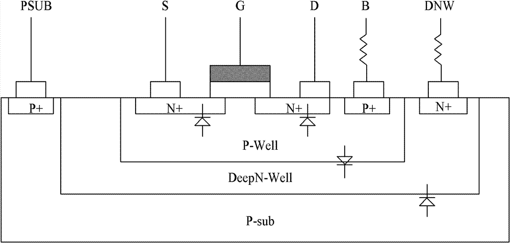
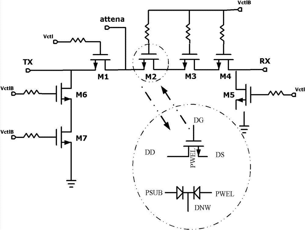
[0009] With the continuous improvement of CMOS process technology, the receiving / transmitting switch, which was difficult to integrate in the RF front-end circuit of the wireless transceiver in the past, is now possible. The invention proposes a high-performance radio frequency transceiver switch circuit which considers the physical device effects of P well / deep N well and deep N well / P substrate, which is different from the conventional design.

[0010] When the MOS tube is turned off, it has a high impedance to radio frequency microwaves, and when it is turned on, it shows a very low impedance and can be used as a switch. In applications such as radio frequency microwave switches or attenuators, its circuit parameters require devices It has a small insertion loss and a large isolation parameter. The MOSFET switch controls the on-off of the circuit through the gate to form a switch circuit. Generally, a single-pole double-throw switch is used. By controlling the DC port of VC...


PUM


Abstract

The invention discloses a radio frequency transceiver switching circuit which comprises CMOS (Complementary Metal Oxide Semiconductor) devices and a duodiode with a P trap / deep N trap and deep N trap / P substrate, wherein the deep N trap and the P trap float. The invention provides the high-performance radio frequency switching circuit which is designed by utilizing a combined circuit model formed by the CMOS devices on four ends and an additional duodiode model which describes the P trap / deep N trap and deep N trap / P substrate, so that all radio frequency indexes such as isolation, insertion loss and linearity can be obtained.

Description

technical field [0001] The invention relates to a semiconductor device, in particular to a radio frequency transceiver switch device. Background technique [0002] In radar, communication and other microwave systems, it is necessary to control the transmission of signals, and various radio frequency microwave control circuits or single chips are required. Microwave and radio frequency switches are one of the core components of this type of transceiver system. In order to reduce insertion loss, Insertion loss is usually reduced by reducing the substrate resistance and setting a stable DC bias potential for the transceiver node. However, the limitation of this method is that the linearity of the transceiver switch is deteriorated. Therefore, it is necessary to provide a new circuit structure design method, which can more accurately design a high-performance radio frequency transceiver switch circuit, and obtain more accurate radio frequency indicators such as isolation, inser...

Claims


Application Information

Patent Timeline
Patent Type & Authority Applications(China)
IPC IPC(8): H03K17/687
Inventor 朱红卫李丹周天舒
Owner SHANGHAI HUAHONG GRACE SEMICON MFG CORP
Learn More