
Ion generator

An ion generator and ion generation technology, applied in electrical components, deodorization, disinfection, etc., can solve the problems of secondary pollution, expensive consumables, poor disinfection effect, etc.

Active Publication Date: 2012-11-14
常州明阳软件科技有限公司 +1
View PDF4 Cites 7 Cited by
  • Summary
  • Abstract
  • Description
  • Claims
  • Application Information

AI Technical Summary

Problems solved by technology

At present, many air purification and disinfection equipment mostly use ultraviolet rays, filtration, cleaning, etc., and there are more or less shortcomings: the disinfection effect of ultraviolet rays is very good, but it is ineffective for harmful gases and particles in the air; The disinfection effect of HEAP and other similar methods is very poor, the filter needs to be replaced in a short time, and the consumables are expensive; the cleaning method needs to add chemicals, the humidity in the air is very high, and it is easy to cause secondary pollution

Method used


Image

  • Ion generator
  • Ion generator

Examples


Embodiment 1

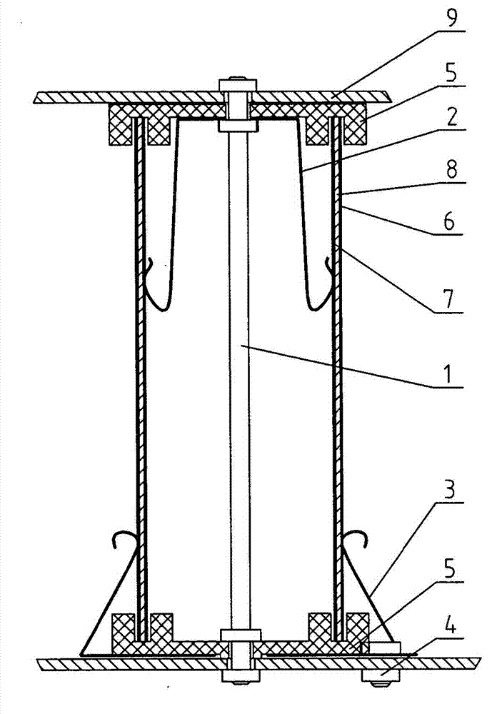
[0016] Such as figure 1 Shown, a kind of ion generator, it comprises fixed stem 1, ion generating tube, inner reed 2, outer reed 3 and outer electrode connecting column 4, and the two ends of fixed stem 1 are respectively equipped with insulator 5, ion The generating tube is embedded on two insulators 5. The ion generating tube is composed of an outer electrode 6, an inner electrode 7 and an insulating insulating layer 8 arranged between the outer electrode 6 and the inner electrode 7. One end of the inner reed 2 is connected to the inner electrode 7. abutting, the other end is electrically connected to the fixed stem 1 , one end of the outer reed 3 is in contact with the external electrode 6 , and the other end is electrically connected to the external electrode connecting column 4 . Both ends of the fixed core column 1 are also installed with fixed tube bases 9 , on which the external electrode connection column 6 is installed. The inner reed 2 is connected to the upper end...

Embodiment 2

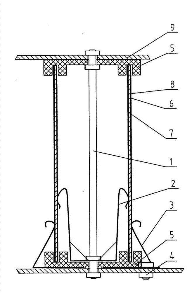
[0019] Such as figure 2 Shown, a kind of ion generator, it comprises fixed stem 1, ion generating tube, inner reed 2, outer reed 3 and outer electrode connecting column 4, and the two ends of fixed stem 1 are respectively equipped with insulator 5, ion The generating tube is embedded on two insulators 5. The ion generating tube is composed of an outer electrode 6, an inner electrode 7 and an insulating insulating layer 8 arranged between the outer electrode 6 and the inner electrode 7. One end of the inner reed 2 is connected to the inner electrode 7. abutting, the other end is electrically connected to the fixed stem 1 , one end of the outer reed 3 is in contact with the external electrode 6 , and the other end is electrically connected to the external electrode connecting column 4 . Both ends of the fixed core column 1 are also installed with fixed tube bases 9 , on which the external electrode connection column 6 is installed. The inner reed 2 is connected to the lower en...


PUM


Abstract

The invention discloses an ion generator and belongs to the technical field of air purification devices. The ion generator comprises a fixed core column, an ion generation tube, an inner reed, an outer reed and an outer electrode connecting column. Insulators are respectively arranged at two ends of the fixed core column, the ion generation tube is embedded in the two insulators, the ion generation tube is composed of an outer electrode, an inner electrode and an isolation insulating layer arranged between the outer electrode and the inner electrode, one end of the inner reed is connected with the inner electrode in butting mode, the other end of the inner reed is electrically connected with the fixed core column, one end of the outer reed is connected with the outer electrode in butting mode, and the other end of the outer reed is electrically connected with the outer electrode connecting column. The ion generator can be used for sterilizing and purifying air, is good in sterilization and purification effects, and cannot generate secondary pollution.

Description

technical field [0001] The invention relates to an ion generator and belongs to the technical field of air purification devices. Background technique [0002] At present, with the gradual popularization of the concept of environmental protection, people are exploring various new technologies for air purification and disinfection. At present, many air purification and disinfection equipment mostly use ultraviolet rays, filtration, cleaning, etc., and there are more or less shortcomings: the disinfection effect of ultraviolet rays is very good, but it is ineffective for harmful gases and particles in the air; The disinfection effect of HEAP and other similar methods is very poor, the filter needs to be replaced in a short time, and the consumables are expensive; the cleaning method needs to add chemicals, and the humidity in the air is very high, which is prone to secondary pollution. [0003] Inspired by the fresh air in thunderstorm weather, the method of using gas ionizat...

Claims


Application Information

Patent Timeline
IPC IPC(8): H01T23/00A61L9/22
Inventor 朱阳明朱阳光孙旭东苏俊锋
Owner 常州明阳软件科技有限公司
Learn More