Thrust valve device

A valve device and thrust technology, applied in the direction of valve device, sliding valve, engine components, etc., can solve the problems of reducing sealing torque and valve stem operating torque, assembly difficulties, etc., to reduce pressure, prolong the life of parts, and reduce operation The effect of torque

Inactive Publication Date: 2012-11-14
周逸亭
View PDF0 Cites 0 Cited by
  • Summary
  • Abstract
  • Description
  • Claims
  • Application Information

AI Technical Summary

Problems solved by technology

[0005] The purpose of the present invention is to address the deficiencies of the prior art, to provide a thrust valve device, which can reduce the sealing torque and valve stem operating torque, prolong the life of related parts and solve the problem of difficult assembly

Method used


Image

  • Thrust valve device
  • Thrust valve device
  • Thrust valve device

Examples


Embodiment Construction

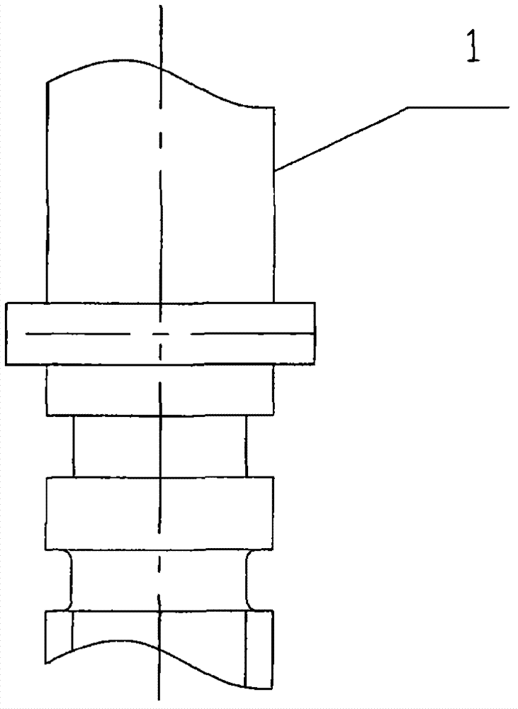
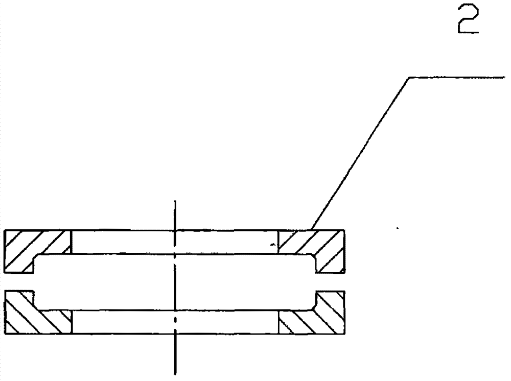
[0018] figure 1 and figure 2 Shown is the valve stem and thrust ring in the existing thrust valve device mentioned in the previous background technology section, from which it can be seen that the thrust protrusion on the valve stem 1 and the thrust concave on the thrust ring 2 The cross-section of the groove is rectangular, and when the two are in matching use, their mutual contact is surface contact, the friction force is large, the torque to operate the valve stem 1 is large, and the wear of the parts affects the service life; because the cross-section is rectangular, it is difficult to install .

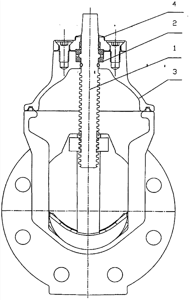
[0019] In the present invention, in order to reduce the operating torque of the valve stem 1, the contact friction between the thrust protrusion and the thrust groove is reduced, such as Figure 5 and Figure 6 As shown, the upper outer peripheral surface of the valve stem 1 is radially provided with a thrust protrusion whose cross-section is an arc of R angle; Arc thrust gr...


PUM


Abstract

The invention discloses a thrust valve device, which consists of a valve stem, a thrust ring, a bonnet and a shaft cover. The thrust ring is embedded in a ring concave hole at the top of the bonnet and is fixed by the shaft cover. The valve stem penetrates through the bonnet, the thrust ring and the center hole of the shaft cover and is limited by the thrust ring to a position which is coaxial with the vertical centerline of the valve. A thrust bulge with a section being an R-degree circular arc is arranged in the radial direction of the outer circumference of the upper part of the valve stem. The inner circumference of the thrust ring is arranged to be a thrust groove with a section being an R-degree circular arc. The thrust bulge on the valve stem is matched with the thrust groove on the thrust ring. The thrust valve device provided by the invention has the advantages that since the R-degree circular arcs of the thrust bulge and the thrust groove are in fit with each other, when the thrust bulge and the thrust groove are in fit with each other through external force during installation and use, the axis of the valve stem can be prevented from being deviated from the vertical centerline of the valve and energy loss is not caused to the force applied to the valve stem because of the deviation of the axis of the valve stem.

Description

【Technical field】 [0001] The invention relates to a valve, in particular to a thrust valve device capable of realizing the operation function of a concealed rod. 【Background technique】 [0002] The valves widely used in the pipeline network system are mostly gate valves, also known as gate valves and gate valves, which drive the closing member (disc) to move along the vertical direction of the centerline of the valve seat through the valve stem to cut off the medium flow in the pipeline. [0003] Among them, in the hidden stem gate valve, the transmission thread that drives the closing part is set at the lower end of the valve stem. The valve stem can only rotate and cannot be lifted, which is very beneficial to reduce the volume, weight and installation position of the valve. [0004] The thrust device of the concealed stem gate valve currently used has a rectangular cross-section of the thrust protrusion on the valve stem and the thrust groove on the thrust ring. When the ...

Claims


Application Information

Patent Timeline
Patent Type & Authority Applications(China)
IPC IPC(8): F16K3/30
Inventor 周逸亭
Owner 周逸亭
Why Eureka
Try Eureka