
Method and device for detecting optical time domain detection signal

A detection device and a technology for detecting signals, which are applied in the field of optical communication, can solve problems such as the limited ability to improve the dynamic range, and achieve the effect of high dynamic range, high resolution, and improved dynamic range

Inactive Publication Date: 2012-10-31
HUAWEI MARINE NETWORKS CO LTD
View PDF2 Cites 24 Cited by
  • Summary
  • Abstract
  • Description
  • Claims
  • Application Information

AI Technical Summary

Problems solved by technology

[0015] Coherent detection technology currently only uses auxiliary methods such as multiple accumulation and digital filtering to improve the dynamic range, and the ability to improve the dynamic range at the level of digital signal processing is limited

Method used


Image

  • Method and device for detecting optical time domain detection signal
  • Method and device for detecting optical time domain detection signal
  • Method and device for detecting optical time domain detection signal

Examples


Embodiment Construction

[0042] Figure 7a It is a block diagram of a detection device for correlated coherent optical time-domain detection signals proposed in Embodiment 1 of the present invention. Figure 7a The key signal flows shown in are annotated as follows:

[0043] ① Detection of pulse sequence optical signals;

[0044] ② local oscillator light;

[0045] ③Detect the backscattered light signal generated by the transmission of pulse sequence light in the optical fiber;

[0046] ④ Digital signal after coherent reception of local oscillator light and backscattered light signal;

[0047] ⑤ digital form of detection pulse sequence;

[0048] ⑥ OTDR signal after correlation calculation.

[0049] The continuous coherent optical signal emitted by the coherent light source 701 is divided into two beams by the first coupler 702 , one beam enters the modulator 703 as probe light, and the other beam enters the coherent receiver 706 as local oscillator light.

[0050] The modulator 703 modulates the ...


PUM


Abstract

The invention provides a detection device of an optical time domain detection signal (OTDR, Optical Time Domain Reflectometry) and a related coherent detection method of the optical time domain detection signal. The method comprises the following steps of: modulating detection light according to a related code pattern sequence to generate a pulse sequence optical signal, and inputting the pulse sequence optical signal into a detected optical fiber; receiving back scattering light from the detected optical fiber, carrying out coherent processing on the back scattering light and local oscillator light, and converting an optical signal obtained after the coherent processing into a digital signal; and carrying out digital related processing on the digital signal and the related code pattern sequence to obtain and output an optical time domain detection signal. According to the scheme of the invention, the advantages of related and coherent OTDR are integrated, the defects of the related and coherent OTDR are made up, and high dynamic range and high resolution OTDR detection is realized.

Description

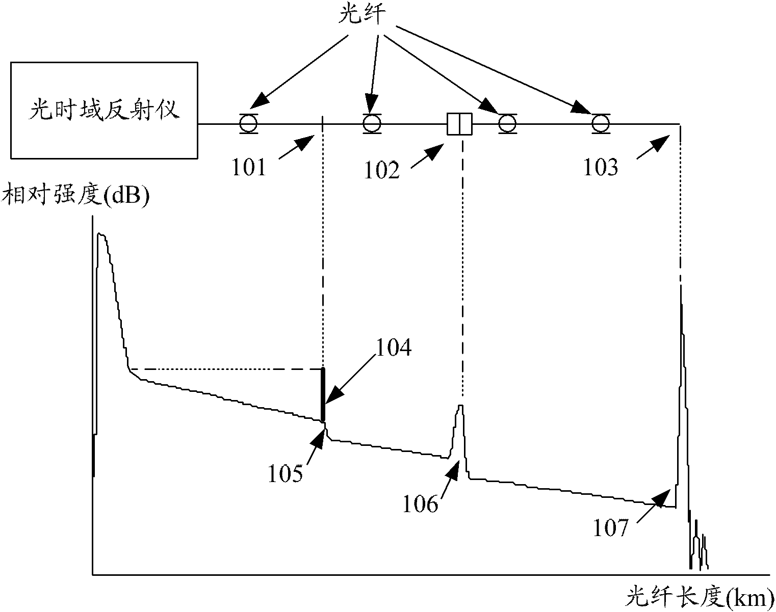
technical field [0001] The invention relates to the technical field of optical communication, in particular to a detection method and device for an optical time domain detection signal. Background technique [0002] Optical Time-Domain Reflectometry (OTDR, Optical Time-Domain Reflectometry) is made according to the principle of backscattering and reflection of light, and uses the backscattered light generated when light propagates in the optical fiber to obtain attenuation information, which can be used to measure optical fiber attenuation, Splice loss, fiber fault point location, and understanding the loss distribution along the length of the fiber, etc. Due to the non-uniform density of the fiber material, the non-uniform doping composition and the defects of the fiber itself, when the light is transmitted in the fiber, every point along the length of the fiber will cause scattering. The optical time domain reflectometer records the scattered light intensity collected at ...

Claims


Application Information

Patent Timeline
IPC IPC(8): H04B10/08
CPCH04B10/071G01M11/3118H04B2210/074H04B10/61G01M11/3136
Inventor 胡颖新王光军陈冀兵
Owner HUAWEI MARINE NETWORKS CO LTD
Learn More