
Oily sludge treatment process and device

A technology for sludge treatment and oil sludge, applied in sludge treatment, water/sludge/sewage treatment, chemical instruments and methods, etc., can solve the problems of expensive equipment, difficult to handle dross, low production efficiency, etc., and achieve Complete oil-water separation, complete separation, and fast processing effect

Inactive Publication Date: 2013-10-16
周利坤
View PDF8 Cites 2 Cited by
  • Summary
  • Abstract
  • Description
  • Claims
  • Application Information

AI Technical Summary

Problems solved by technology

Commonly used equipment for oil sludge treatment includes dehydration devices, filtration devices, pressurization devices, incineration devices, etc., most of which have certain problems. Some equipment has relatively low production efficiency, and some equipment produces dross that is difficult to handle. Relatively big difficulty
For example, Daqing Oilfield imported a set of oily sludge treatment equipment from the UK, but the utilization rate has been very low since the purchase for 6 years; in addition, the whole set of equipment is expensive (only one 15m 3 The price of a centrifuge with a processing capacity per hour is as high as 150,000 euros), and this equipment has not been promoted and used in China

Method used


Image

  • Oily sludge treatment process and device
  • Oily sludge treatment process and device
  • Oily sludge treatment process and device

Examples


Embodiment Construction

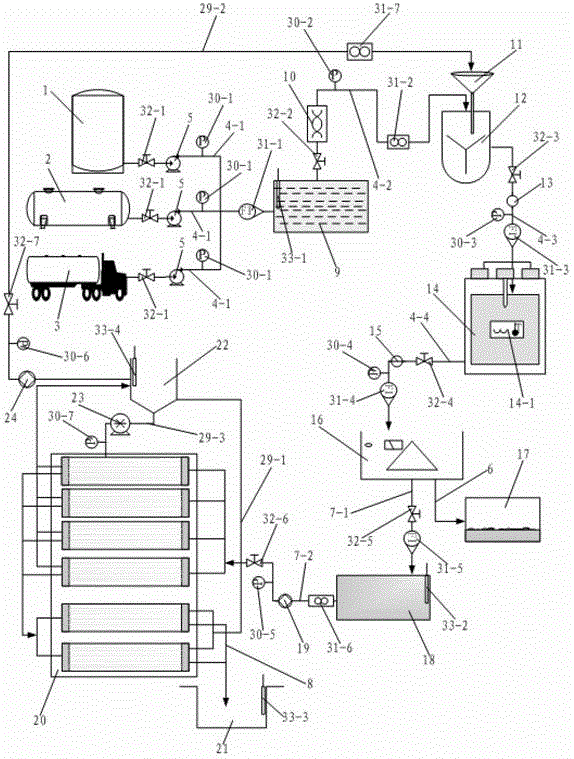
[0061] Such as figure 1 As shown, the oily sludge treatment process of the present invention comprises the following steps:

[0062] Step 1. Add water and stir to dilute: the oily sludge in the oil tank is stored in the sludge storage tank 9 through the centrifugal pump 5, enters the funnel 11 above the mixer 12 through the screw pump 10, enters the mixer 12 through the funnel 11, and the mixer 12 pairs Oily sludge is diluted with water;

[0063] Step 2, ultrasonic demulsification: the stirred and diluted oily sludge enters the ultrasonic demulsification equipment 14 through the first in-line pump 13, and the ultrasonic demulsification equipment 14 performs demulsification treatment on the oily sludge;

[0064] Step 3, solid-liquid separation: the oily sludge after demulsification enters the centrifuge 16 through the second in-line pump 15, and the centrifuge 16 performs solid-liquid separation treatment on the oily sludge to obtain sludge and oily sewage, and the sludge is d...


PUM


Abstract

The invention discloses an oily sludge treatment process and a device. The oily sludge treatment process includes the steps of watering and stirring for dilution, ultrasonic wave demulsification, solid-liquid separation and oil-water separation. The device comprises an oily sludge treatment system, an automatic control system and a power supply device, wherein the oily sludge treatment system comprises a stirrer, an ultrasonic wave demulsification device, a centrifugal machine, a ultra-filtration system, an oily sludge storage tank, a sludge tank, a centrifugation liquid storage tank, a concentration tank and a filtrate tank, the stirrer is used for adding water into oily sludge for diluting the oily sludge, the ultrasonic wave demulsification device is used for demulsifying the oily sludge, the centrifugal machine is used for performing solid-liquid separation to the oily sludge, the ultra-filtration system is used for performing oil-water separation to the oily sludge, the oily sludge storage tank is used for storing the oily sludge, the sludge tank is used for storing the sludge, the centrifugation liquid storage tank is used for storing oily sewage, the concentration tank is used for storing oil, and the filtrate tank is used for storing water. According to the oily sludge treatment process and the device, the design is novel and reasonable, achievement costs are low, the treatment speeds are fast, the separation of the oil, the sludge and the water is thorough, the resource utilization of the oily sludge is achieved, and environmental pollution and resource waste are reduced.

Description

technical field [0001] The invention relates to the technical field of oily sludge treatment, in particular to an oily sludge treatment process and equipment. Background technique [0002] Oily solid waste is produced in oil extraction, transportation, refining, oily sewage treatment and oil tank cleaning, which is called oily sludge. Generally, the oil content is 10% to 50%, and the water content is about 40% to 90%. It is characterized by high oil content and heavy oil components. Oily sludge is a large and wide-ranging pollution source, containing pathogenic bacteria, parasites (eggs), heavy metals, salts, polychlorinated biphenyls, dioxins, radionuclides and other refractory toxic and harmful substances. At present, in my country's petrochemical industry, an average of 800,000 tons of tank bottom sludge and pool bottom sludge are produced every year. A large amount of oily sludge is produced, and the potential impact on the environment is increasing. The sludge produce...

Claims


Application Information

Patent Timeline
Patent Type & Authority Patents(China)
IPC IPC(8): C02F11/00
Inventor 周利坤战仁军李悦贾贤补
Owner 周利坤
Learn More