
Pneumatic gurney flap based on plasma wall surface jet flow

A technology of plasma and Gurney flaps, applied in the direction of affecting the airflow flowing through the surface of the aircraft, aircraft parts, aircraft control, etc., can solve the problems of reducing the fatigue strength of the wing, increasing the extra weight of the aircraft, and achieving low power consumption , light weight, easy to install

Active Publication Date: 2015-06-17
BEIHANG UNIV
View PDF7 Cites 0 Cited by
  • Summary
  • Abstract
  • Description
  • Claims
  • Application Information

AI Technical Summary

Problems solved by technology

However, in order to achieve this, complex mechanical mechanisms are required, which not only add extra weight to the aircraft, but also reduce the fatigue strength of the wings

Method used


Image

  • Pneumatic gurney flap based on plasma wall surface jet flow
  • Pneumatic gurney flap based on plasma wall surface jet flow
  • Pneumatic gurney flap based on plasma wall surface jet flow

Examples


Embodiment Construction

[0032] The present invention will be further described in detail with reference to the accompanying drawings and embodiments.

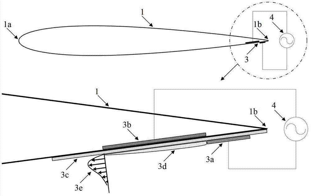
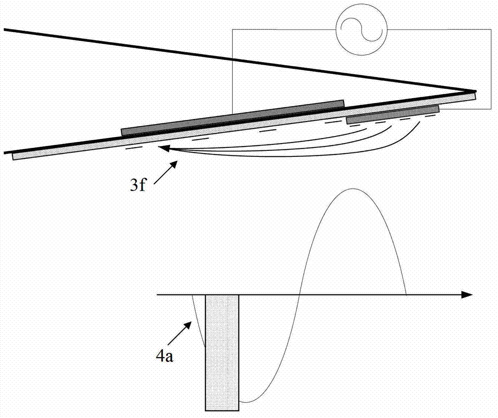
[0033] The invention proposes an aerodynamic Gurney flap based on plasma wall jet flow, which is realized by a specific layout of plasma exciters on the wing. The plasma actuator is attached to the pressure surface of the wing near the trailing edge. Under the condition of free flow, the power of the plasma actuator is turned on, and the wall jet induced by it is opposite to the direction of the free flow. The two interact. A stable recirculation zone is formed at the trailing edge of the wing to achieve the control effect of the aerodynamic Gurney flap. The wind tunnel force test shows that the aerodynamic Gurney flap based on the plasma wall jet proposed by the present invention can effectively increase the lift of the airfoil, the wing and the aircraft. The aerodynamic Gurney flap of the present invention can also be opened and closed at any time ...


PUM


Abstract

The invention provides a pneumatic gurney flap based on plasma wall surface jet flow, which is implemented by the interaction between incoming flow and the horizontal wall surface jet flow which is generated by the induction of a plasma exciter. The plasma exciter attaches to the part close to the back edge of a wing pressure surface, and comprises a naked electrode, a covered electrode and an insulating medium located between the two electrodes, wherein the naked electrode is close to the back edge of a wing, and the covered electrode is located at the upstream of the naked electrode. A high-voltage and high-frequency sine alternating-current power supply is applied between the naked electrode and the covered electrode to induce to generate the wall surface jet flow pointing to an upstream direction to be interacted with the free incoming flow, and then a stable reflowing region is formed at the part close to the back edge of the wing pressure surface, so that the pressure of the wing pressure surface and the suction force of a suction force surface are increased, and further, the hoisting force of the wing is improved. The lift augmentation effect and the mechanism of the pneumatic gurney flap disclosed by the invention are similar to those of the conventional mechanical gurney flap, but the pneumatic gurney flap disclosed by the invention has the advantages of light weight, simple device and small interference on a flow field boundary layer, and can realize the active and non-steady control on the wing.

Description

technical field [0001] The invention relates to an aerodynamic Gurney flap, in particular to the aerodynamic Gurney flap realized by the wall jet induced by a plasma actuator placed on the pressure surface of the wing. Background technique [0002] In the field of aeronautical engineering, a Gurney flap is a device that effectively increases the lift of an aircraft. Such as figure 1 As shown, the Gurney flap 2 is usually made of a spoiler and is vertically attached to the pressure surface of the wing near the trailing edge 1b. The height of the Gurney flap is usually 0.5% to 3% of the root chord length of the wing, but it can greatly increase the lift of the wing. Judging from the flight status of the Gurney flap application, its most effective moment is the takeoff and landing phase of the aircraft, which can greatly shorten the takeoff and landing distance of the aircraft. But in the cruising phase of the aircraft, because it is in a stable state, there is no need to in...

Claims


Application Information

Patent Timeline
Patent Type & Authority Patents(China)
IPC IPC(8): B64C21/00
Inventor 冯立好王晋军崔宏昭刘亚光史涛瑜
Owner BEIHANG UNIV
Learn More