Optical fiber connector forming die and manufacturing method thereof

An optical fiber connector and forming mold technology, which is applied to the optical fiber connector forming mold and its production field, can solve the problems that the precision of the forming surface is difficult to meet the requirements, and the bottom edge of the forming surface is difficult to be processed in place, etc. The effect of roughness reduction and optical signal loss reduction

Active Publication Date: 2012-10-31
FS COM LTD
View PDF5 Cites 0 Cited by
  • Summary
  • Abstract
  • Description
  • Claims
  • Application Information

AI Technical Summary

Problems solved by technology

[0003] Existing optical fiber connector molds are usually integrated, that is, the molding surface of the contact surface of the output end of the optical fiber used to form the optical fiber connector is integrated with other parts of a mold core block, and is blocked by other parts of the mold core. When processing the molding surface, the bottom edge of the molding surface is often difficult to process in place, so the precision of the molding surface used to shape the contact surface of the output end of the optical fiber of the optical fiber connector is difficult to meet the requirements

Method used


Image

  • Optical fiber connector forming die and manufacturing method thereof
  • Optical fiber connector forming die and manufacturing method thereof
  • Optical fiber connector forming die and manufacturing method thereof

Examples


Embodiment Construction

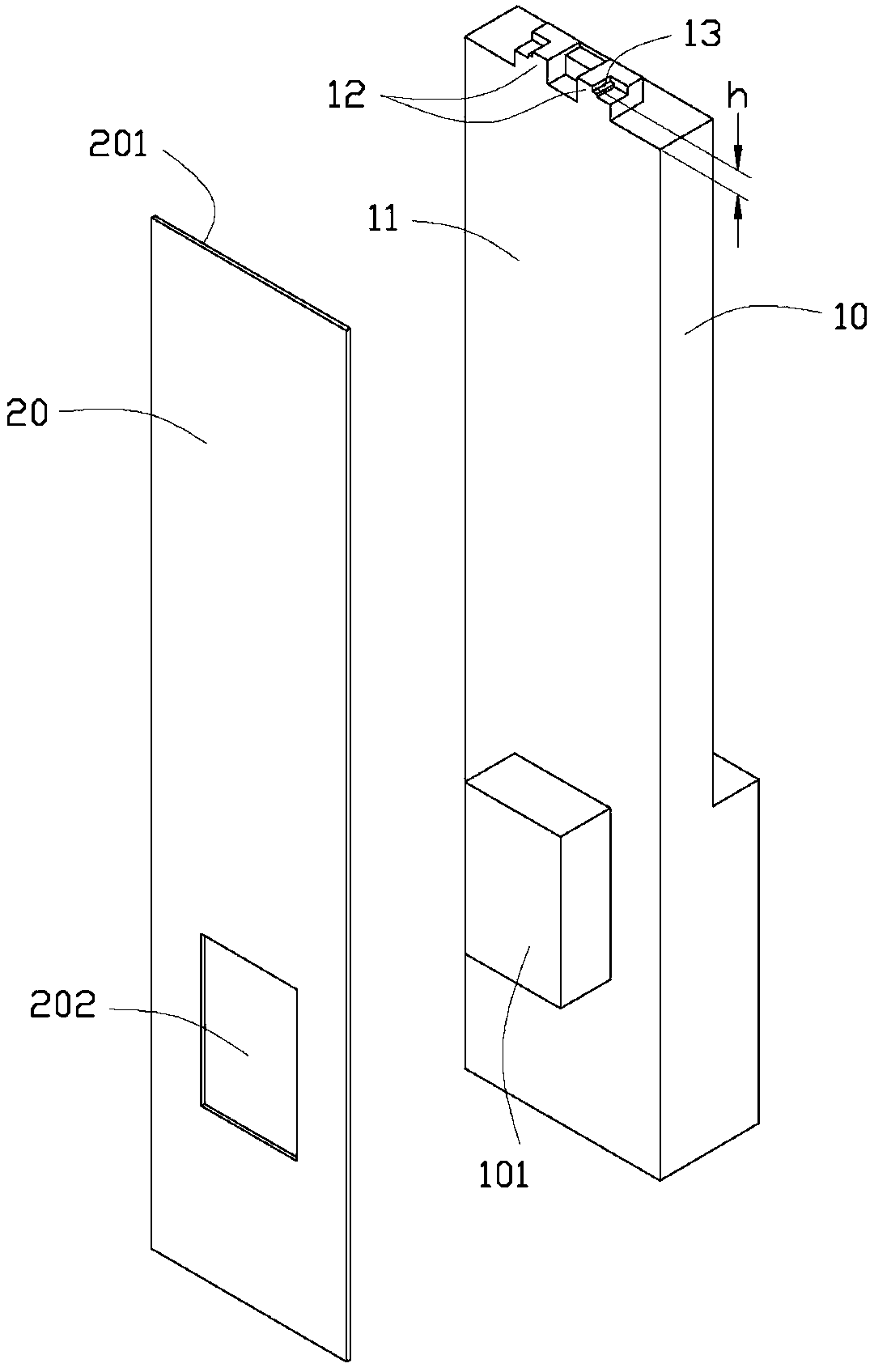
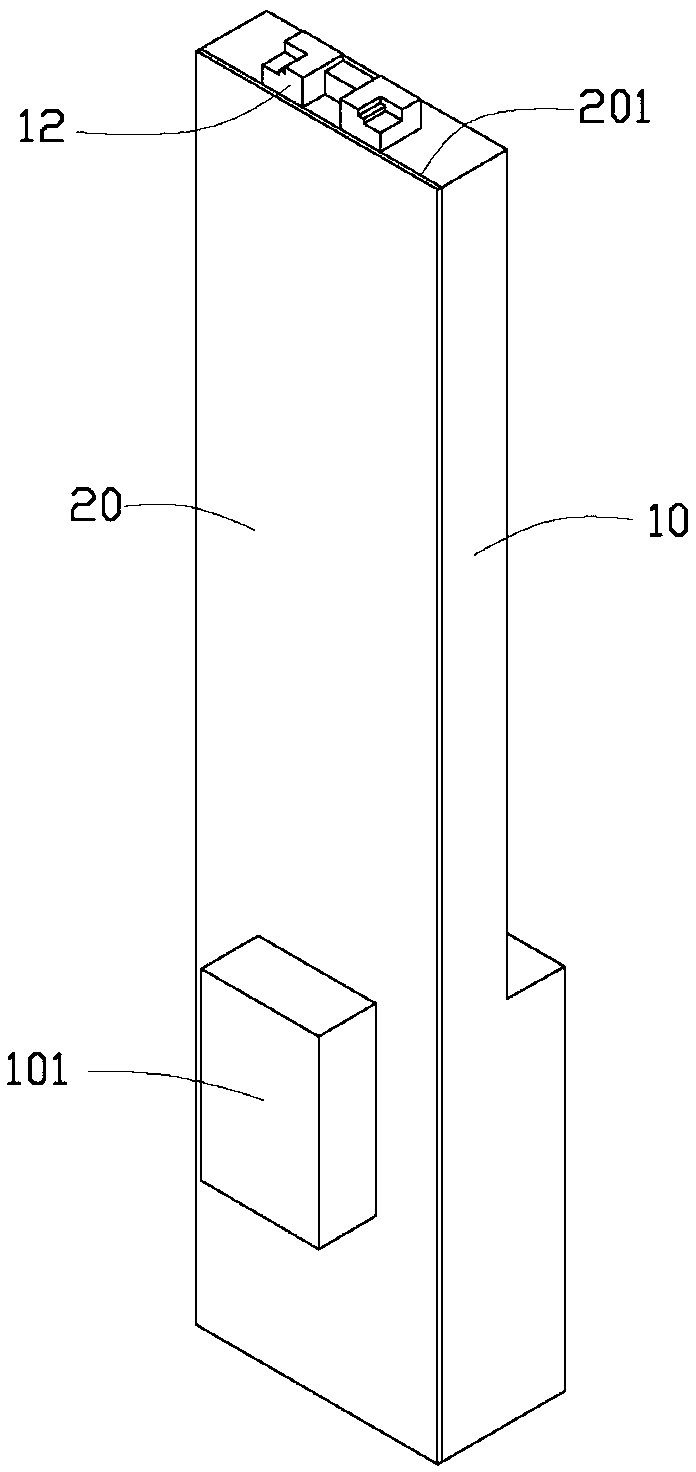
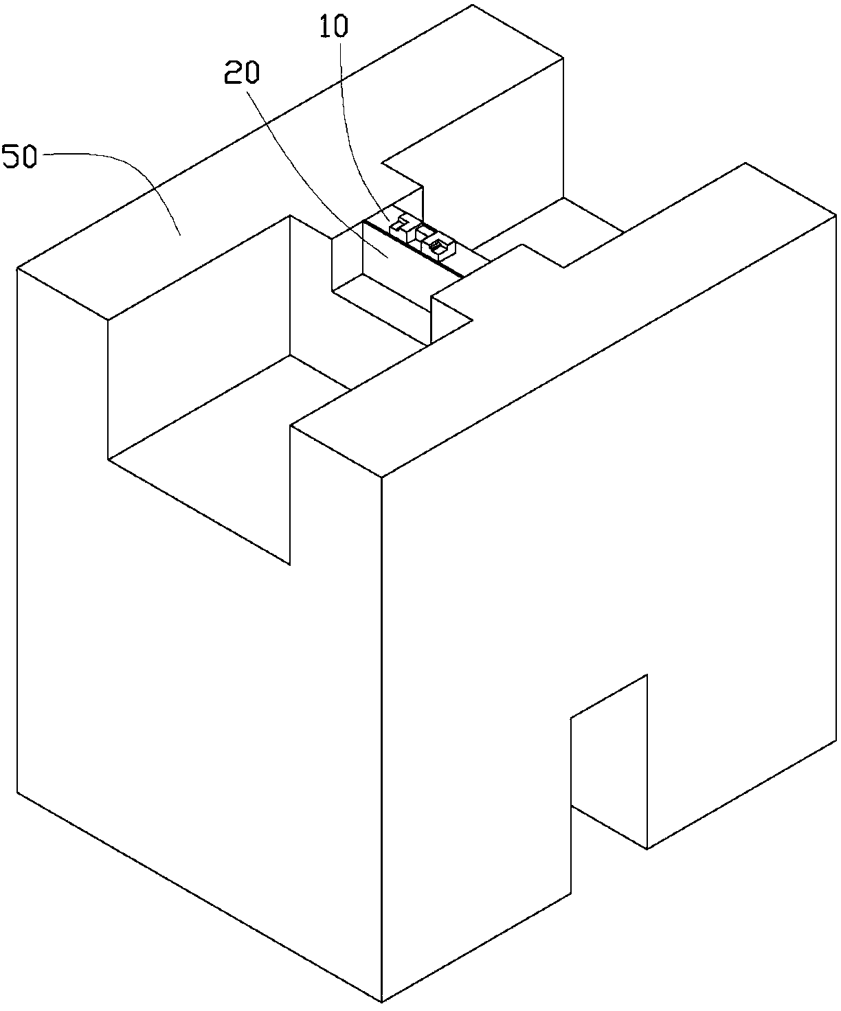
[0023] see Figure 1 to Figure 4 , the optical fiber connector forming mold provided by the embodiment of the present invention includes a mold core block 50 for embedding (see image 3 ) of the insert 10 and a gasket 20 that cooperates with the insert. In this embodiment, the core block 50 is a male core block, which will cooperate with a female core block (not shown) to form an optical fiber connector 60 (see Figure 4 ), that is, the mold core block 50 is only used to form the right part of the A-A line of the optical fiber connector 60 . The insert 10 and the gasket 20 participate in the molding, and only the front and rear parts of the contact surface of the output end of the optical fiber in the optical fiber connector 60 are molded, see Figure 4 Arrow B points to the square area.

[0024] Please refer to figure 1 and figure 2 , the insert 10 includes a sidewall surface 11 and two molding surfaces 12 extending from the surface 11 . The two molding surfaces 12 are...


PUM


Abstract

The invention relates to an optical fiber connector forming die comprising an insert used to be embedded into a mold core block and a gasket matching the insert. The insert comprises a surface, and a forming surface extending from the surface and used for forming a contact surface of an optical fiber output terminal. The forming surface is subjected to mirror finishing. The gasket is adhered to the surface of the insert. One side of the gasket is aligned with one edge of the forming surface. The side of the gasket and the forming surface of the insert are used together to form a side wall in which the optical fiber output terminal of the optical fiber connector is positioned. The invention also provides a manufacturing method of the optical fiber connector forming die.

Description

technical field [0001] The invention relates to mold processing and assembly, in particular to an optical fiber connector forming mold and a manufacturing method thereof. Background technique [0002] Fiber optic connectors transmit signals through optical fibers. The optical fiber connector usually has a through hole and some mechanical components, such as an L-shaped step, to guide and fix the optical fiber. The precision of the contact surface used to contact the output end of the optical fiber in the optical fiber connector, such as surface roughness, thickness dimension, etc., is highly required, because it will affect the efficiency of light transmission. [0003] Existing optical fiber connector molds are usually integrated, that is, the molding surface of the contact surface of the output end of the optical fiber used to form the optical fiber connector is integrated with other parts of a mold core block, and is blocked by other parts of the mold core. When process...

Claims


Application Information

Patent Timeline
Patent Type & Authority Applications(China)
IPC IPC(8): B29C33/00B23P15/24
Inventor 许嘉麟
Owner FS COM LTD
Why Eureka
Try Eureka