Electromagnetic flow control valve and high pressure fuel supply pump using same
A technology of flow control valve and high-pressure fuel, which is applied to fuel injection pumps, fuel injection devices, special fuel injection devices, etc., and can solve problems such as the cross-sectional area of difficult fuel passages
- Summary
- Abstract
- Description
- Claims
- Application Information
AI Technical Summary
Problems solved by technology
Method used
Image
Examples
Embodiment 1
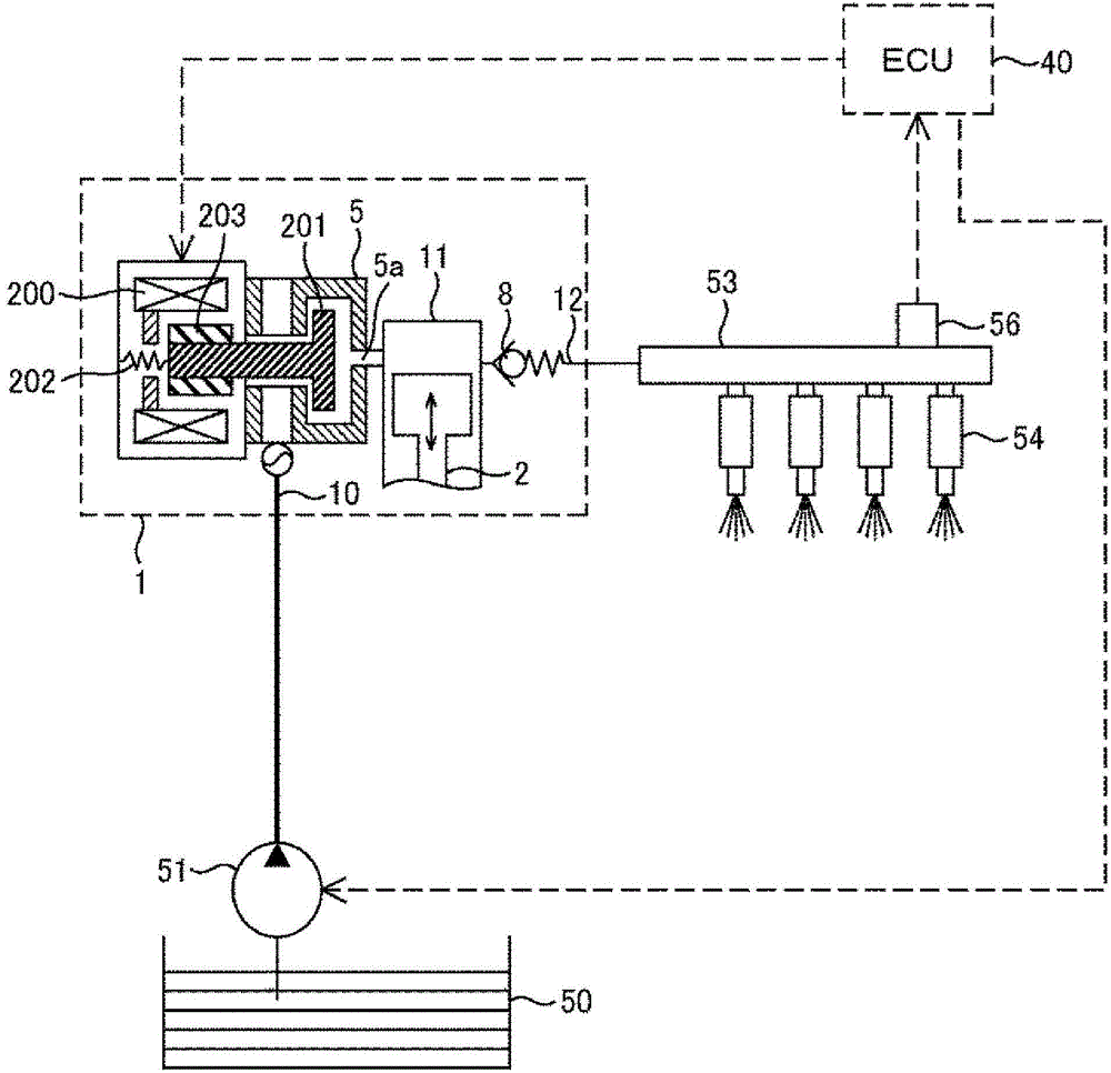
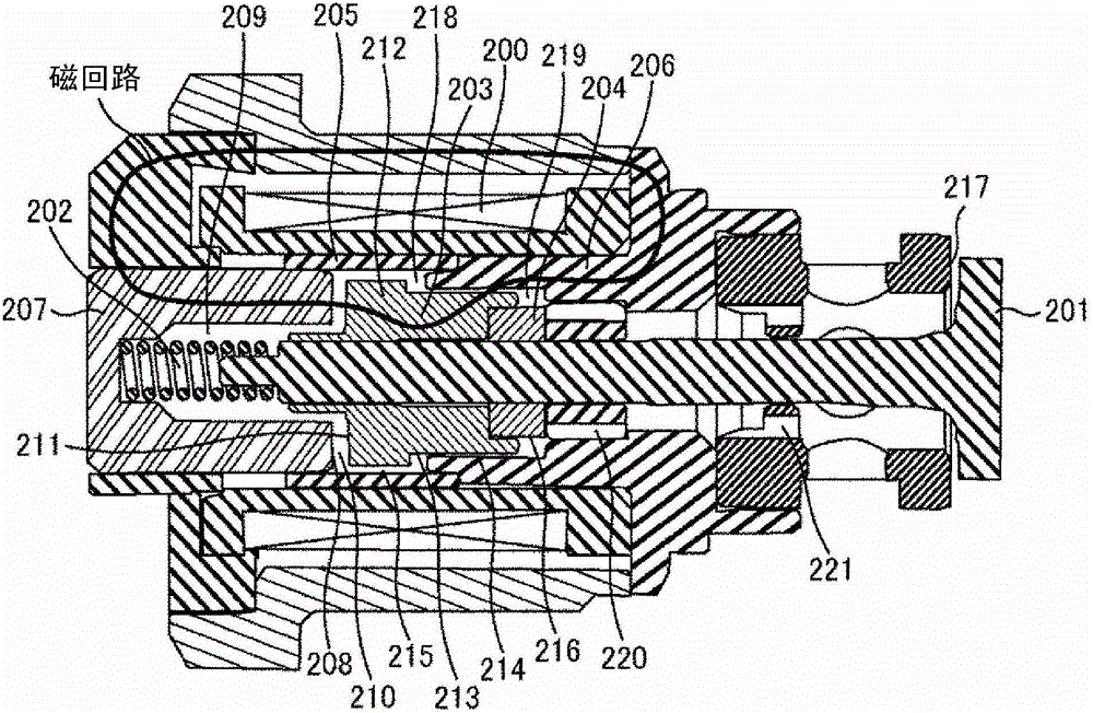
[0029] figure 1 An overall configuration of a system using a normally-open solenoid valve implementing Embodiment 1 and Embodiment 2 of the present invention is shown. A portion surrounded by a dotted line represents a pump housing 1 of the high-pressure fuel supply pump, and the mechanisms and components shown in the dotted line are integrated therein. A suction port 10 , a pressurization chamber 11 , and a fuel discharge passage 12 are formed in the pump housing 1 . An electromagnetic valve 5 and a discharge valve 8 are provided in the suction port 10 and the discharge passage 12, and the discharge valve 8 constitutes a check valve for restricting the flow direction of fuel. In addition, between the suction port 10 and the pressurized chamber 11 , the solenoid valve 5 is held by the pump casing 1 and a solenoid coil 200 , an armature 203 , and a spring 202 are disposed. A force is applied to the valve core 201 through the spring 202 in the direction of valve opening. As a...
Embodiment 2
[0048] image 3 A cross section of the solenoid valve according to the second embodiment of the present invention when the valve is opened is shown. The shape of the valve body 201 is different from Example 1, and it is divided into two members of the valve body part 201a and the rod part 201b in this Example. The rod portion 201b bears the force exerted by the spring 202 along the valve opening direction, and the stroke is limited by the contact of the stopper 204 with the inside of the solenoid valve. On the other hand, the spool portion 201a receives an urging force in the valve closing direction from the spool spring 222, and presses against the front end of the rod portion 201b. Here, the urging force of the spring 202 is set to be greater than the urging force of the spool spring 222, and when the electromagnetic coil 200 is OFF, the valve plate 217a and the spool portion 201a are kept in the open state without contact. When the pump is in the compression process, if t...
Embodiment 3
[0051] Figure 4 The whole structure of the system of the normally closed electromagnetic valve which implements Example 3 and Example 4 of this invention is shown. The normally closed mode is the opposite of the normally open mode. It is a solenoid valve mode in which the state of the solenoid coil is OFF and the valve is closed, and the state of the solenoid coil is ON to form the valve open state. and figure 1 The arrangement of components inside the solenoid valve 30 is different from that shown in the normally open mode. An electromagnetic coil 300 , an armature 303 , and a spring 302 are arranged inside the electromagnetic valve 30 . A force is applied to the valve core 301 in the direction of closing the valve through the spring 302 . Accordingly, when the electromagnetic coil 300 is OFF, the valve element 301 is in a closed state. The injector 54 and the pressure sensor 56 are attached to the common rail 53 as in the case of the normally open system. The injector ...
PUM
 Abstract
Description
Claims
Application Information
 - R&D
- Intellectual Property
- Life Sciences
- Materials
- Tech Scout
- Unparalleled Data Quality
- Higher Quality Content
- 60% Fewer Hallucinations
Browse by: Latest US Patents, China's latest patents, Technical Efficacy Thesaurus, Application Domain, Technology Topic, Popular Technical Reports.
© 2025 PatSnap. All rights reserved.Legal|Privacy policy|Modern Slavery Act Transparency Statement|Sitemap|About US| Contact US: help@patsnap.com


