Method for controlling winding current waveforms of switched reluctance motor

A technology of switched reluctance and winding current, which is applied in the direction of AC motor control, electronic commutation motor control, current controller, etc., can solve the problems of large electromagnetic noise, increased current variation range, and unsmooth waveform, and achieve electromagnetic noise Small, smooth current waveform effect

Inactive Publication Date: 2015-05-27
TAIYUAN UNIV OF TECH
View PDF5 Cites 0 Cited by
  • Summary
  • Abstract
  • Description
  • Claims
  • Application Information

AI Technical Summary

Problems solved by technology

Based on the above reasons, the current variation range under the current chopping control mode increases, the waveform is seriously not smooth, and the electromagnetic noise is large

Method used


Image

  • Method for controlling winding current waveforms of switched reluctance motor
  • Method for controlling winding current waveforms of switched reluctance motor
  • Method for controlling winding current waveforms of switched reluctance motor

Examples


Embodiment Construction

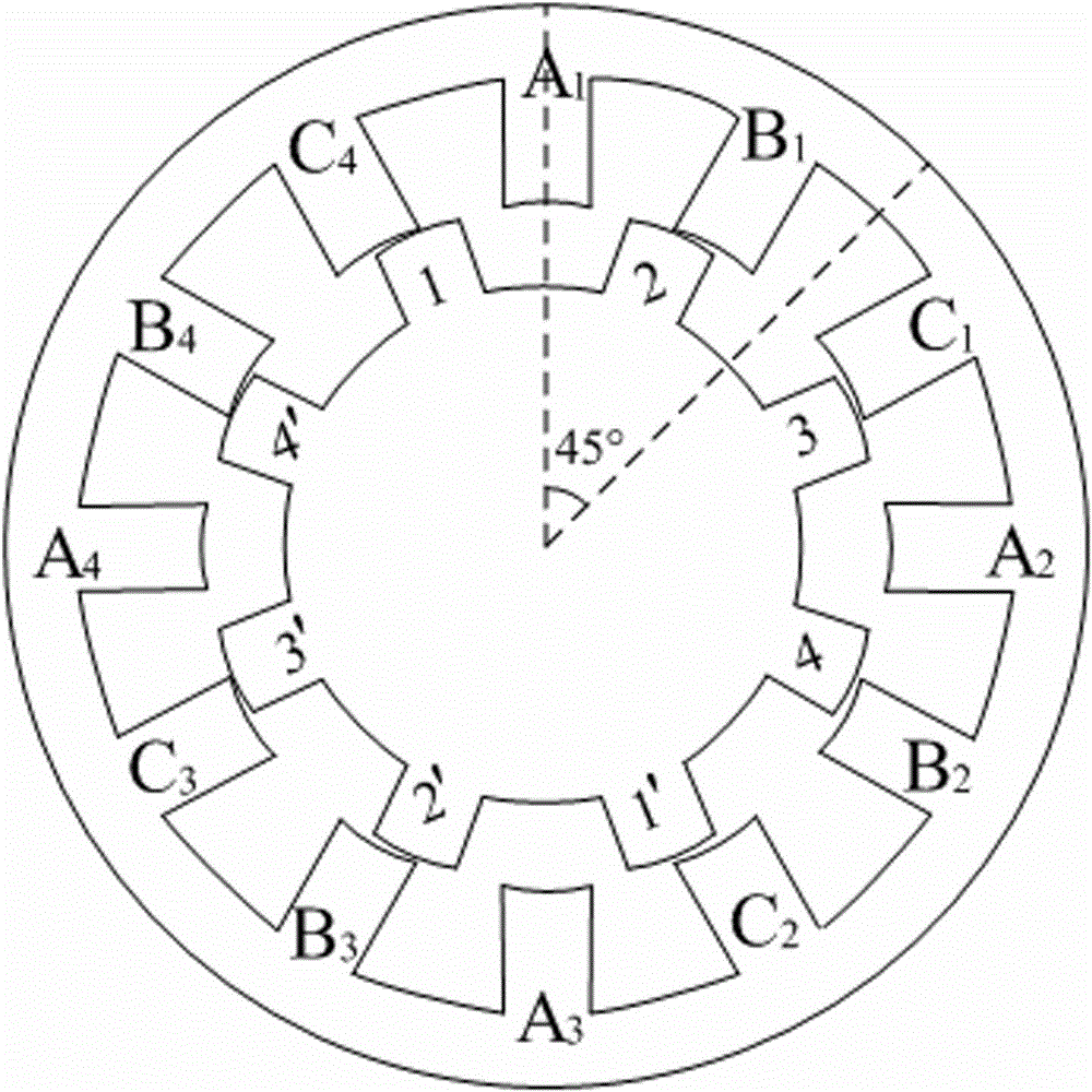
[0014] Taking a three-phase switched reluctance motor with 12 / 8 poles as an example, the embodiment of the present invention is described in detail:

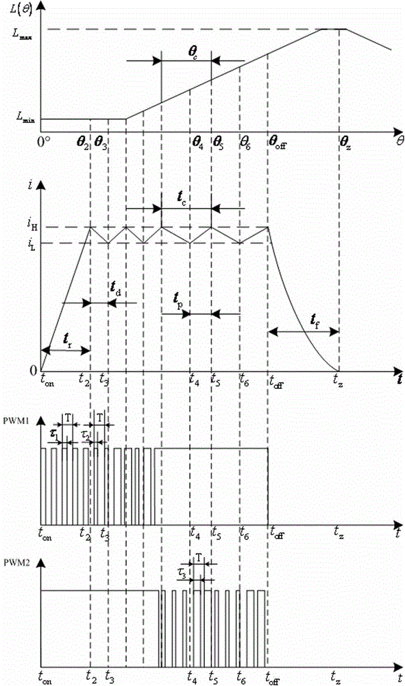
[0015] To implement this control method, the digital signal processor , the switch tube of the power conversion circuit adopts a fully controlled power semiconductor device . The three-phase winding of the three-phase switched reluctance motor includes A phase, B phase and C phase. figure 1 There are four curves in total, among them, is the inductance curve of phase A winding, i is the corresponding phase A winding current waveform, and are the upper switching tube and the lower switching tube connected in series with the A-phase winding respectively Drive signal curve. like figure 1 As shown, the phase A winding curve minimum inductance region of the The position, that is, the position where the stator salient pole of the A phase winding is aligned with the center of the rotor groove starts to be energized, ...


PUM


Abstract

The invention relates to a method for controlling winding current waveforms of a switched reluctance motor. The stepping angle of the switched reluctance motor is 15 degrees, the polar distance angle of a rotor is 45 degrees, the connectivity cycle of each phase winding is an interval when a rotor salient pole turns to pass a stepping angle, the opening angle of the phase winding is fixed at a position, namely a zero degree position, a stator salient pole of the switched reluctance motor is aligned to the center of a rotor groove at the zero degree position, the turn-off angle is fixed at a position where a rotor turns to pass a stepping angle along a rotating direction from the zero degree position, each phase winding is controlled by two switches, the switches are in a series connection with the upper side and the lower side of a switched reluctance motor winding coil respectively, within the connectivity cycle of each phase winding, a constant frequency width modulation control method is used for pulse-width modulation (PWM) signals in a current rise area of the phase winding connectivity cycle, a current rise section in a phase winding connectivity cycle chopped wave area and a current decline section in the phase winding connectivity cycle chopped wave area, duty ratios of the PWM signals are different, and in a current decline area out of the phase winding connectivity cycle, upper and lower switch tubes are in an off-state.

Description

technical field [0001] The invention relates to a current control method, in particular to a control method for the winding current waveform of a switched reluctance motor. Background technique [0002] Switched reluctance motors often adopt current chopping control mode when starting and running at low speed. because send each time Before the signal, it is necessary to collect and judge the fault signal of the system, the start and stop signal of the motor, the forward and reverse signal of the motor, and the position signal of the motor rotor in sequence, determine the conduction phase according to the position signal of the motor, and then determine the control according to the current motor speed. way, after executing the corresponding control program, it will send to the switch tube Signal. When using a general microprocessor as the master , the time to execute the above program will be longer, that is to say T...

Claims


Application Information

Patent Timeline
Patent Type & Authority Patents(China)
IPC IPC(8): H02P6/00H02P6/20H02P6/28H02P25/08
Inventor 曲兵妮宋渊贾会永宋建成
Owner TAIYUAN UNIV OF TECH
Why Eureka
Try Eureka