Rapid connecting type photovoltaic junction box with shelter
A junction box and quick-connect technology, used in photovoltaic power generation, photovoltaic modules, connections where permanent deformation works, etc., can solve problems such as affecting current power, quality differences, and forming open circuits, and achieve reliable electrical connection, reliable performance, Eliminate the effect of deformation
- Summary
- Abstract
- Description
- Claims
- Application Information
AI Technical Summary
Problems solved by technology
Method used
Image


Examples
Embodiment 1
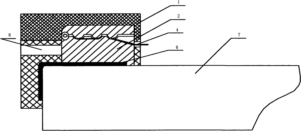
[0036] as follows figure 1 , 2 As shown, the box cover 1 is set to the following shape, which is formed by one-time injection molding. The box cover 1 is surrounded by a thin edge that is clamped with the box body, and the bottom of one side is provided with a protective cover perpendicular to the side of the box cover 1. wing. The shape of the box cover 1 is corresponding to the structure of the box body 2, which can completely occupy the space other than the external circuit components in the box body 2, so as to ensure that there is no extra space for the external circuit during assembly, thereby solving the common thermal expansion of the junction box Cold shrinkage problem. At the same time, the box body 2 is set to be integrally injection-molded into the shape of the box body 2 as shown in the figure by connecting the terminal parts connected by the positioning pin 24 and the plastic material as shown in the figure, and the box body 2 includes positive and negative two...
Embodiment 2
[0040] as follows figure 1 , 2 , 3, the box cover 1 is set to the following shape, one-time injection molding, the box cover 1 has a thin edge around the box body, and the bottom of one side is perpendicular to the side of the box cover 1. wings. The tail of the wings has a stepped structure, and the shape of the box cover 1 is corresponding to the structure of the box body 2, which can completely occupy the space other than the external circuit components in the box body 2, ensuring that there is no redundant external circuit during assembly space, so as to solve the common problem of thermal expansion and contraction deformation of junction boxes. At the same time, the box body 2 is set as shown in the figure, and the terminal part connected by the positioning pin is integrally injected with the plastic material into the shape of the box body 2 as shown in the figure. The box body 2 includes two positive and negative wires. post, the positive and negative terminals are in...
Embodiment 3
[0043] Such as Figure 4 As shown, the lid 1 is set as follows Figure 5 , Figure 6 The shape shown is one-time injection molding. The box cover 1 is surrounded by a thin edge that is clamped with the box body 2, and the bottom of one side is provided with a wing perpendicular to the side of the box cover 1. The box cover 1 The shape corresponds to the structure of the box body 2, and the space other than the components in the box body 2 can be completely occupied, so as to ensure that there is no extra space for the external circuit during assembly, and avoid the problem of thermal expansion and contraction deformation that may occur in the junction box. The box cover 1 is provided with heat conduction blind holes to expedite the dissipation of heat generated by components, especially the diode 5 . At the same time, the box body 2 is set as a terminal Figure 10 , Figure 11 The 21, 22 in it are connected by the positioning pin 24 Figure 9 The terminal part and the pla...
PUM
 Abstract
Description
Claims
Application Information
 - R&D
- Intellectual Property
- Life Sciences
- Materials
- Tech Scout
- Unparalleled Data Quality
- Higher Quality Content
- 60% Fewer Hallucinations
Browse by: Latest US Patents, China's latest patents, Technical Efficacy Thesaurus, Application Domain, Technology Topic, Popular Technical Reports.
© 2025 PatSnap. All rights reserved.Legal|Privacy policy|Modern Slavery Act Transparency Statement|Sitemap|About US| Contact US: help@patsnap.com