
Dispatching system for buses

A dispatching system and bus technology, applied in the field of public transportation control, can solve the problems of no mutual communication mechanism, unreasonable dispatching, no car positioning, etc.

Inactive Publication Date: 2012-10-24
NORTH CHINA ELECTRIC POWER UNIV (BAODING)
View PDF3 Cites 27 Cited by
  • Summary
  • Abstract
  • Description
  • Claims
  • Application Information

AI Technical Summary

Problems solved by technology

[0004] 1. The current bus dispatching system does not have timely feedback on ride information, vehicle driving data collection is unstable, dispatching measures are relatively lagging behind, and bus operating costs are high;
[0005] 2. The existing bus scheduling is manual operation, there is no mutual communication mechanism between the buses on the same road, the information interaction between the bus and the control station is not timely, it is difficult to grasp the situation of vehicles and people flow, and the scheduling is unreasonable;
[0006] 3. The existing public transportation system often adopts the control scheme of fixed-point departure. The interval between two buses is relatively fixed (ten minutes). During peak hours, passengers are crowded, which brings certain difficulties to residents; Passengers are sparse, resulting in a certain waste of resources;
[0007] 4. The existing public transport system does not accurately locate the vehicle. When an accident or danger occurs in the vehicle, it is difficult to carry out rescue work for passengers in the first place, resulting in loss of life and property;
[0008] 5. Although some companies have developed intelligent public transportation systems and have been partially applied, they are still in the state of information islands, with complex structures, and no unified standards and norms have been formed, let alone a unified information platform.
[0009] Therefore, the existing bus dispatching system can no longer meet the needs of the city's growing development, and cannot be recognized by the increasing number of travel residents.

Method used


Image

  • Dispatching system for buses
  • Dispatching system for buses
  • Dispatching system for buses

Examples


Embodiment Construction

[0030] The preferred embodiments will be described in detail below in conjunction with the accompanying drawings. It should be emphasized that the following description is only exemplary and not intended to limit the scope of the invention and its application.

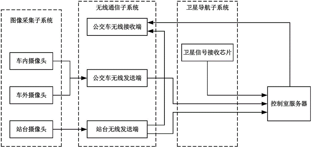
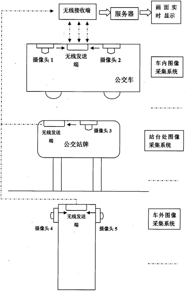
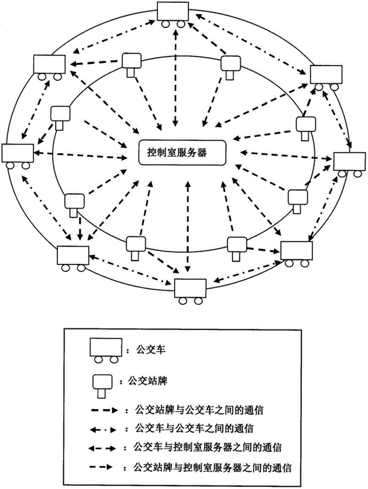
[0031] figure 1 It is a structural diagram of a bus dispatching system provided by the present invention. figure 1 Among them, the bus dispatching system provided by the present invention includes an image acquisition subsystem, a wireless communication subsystem, a satellite navigation subsystem and a control room server. The image acquisition subsystem includes an in-vehicle camera installed inside the bus, an outside camera installed outside the bus, and a platform camera installed on the bus platform. The wireless communication subsystem includes a bus wireless transmitter installed on the bus, a bus wireless receiver installed on the bus, and a platform wireless transmitter installed on the bus platform. The sa...


PUM


Abstract

The invention discloses a dispatching system for buses in the technical field of public traffic control. The dispatching system comprises an image acquiring subsystem, a wireless communication subsystem, a satellite navigation subsystem and a control room server, wherein the image acquiring subsystem comprises an internal camera arranged in a bus, an external camera arranged outside the bus, and a station camera arranged on a bus station; the wireless communication subsystem comprises a bus wireless sending end arranged on the bus, a bus wireless receiving end arranged on the bus, and a station wireless sending end arranged on the bus station; and the satellite navigation subsystem comprises a user side receiving chip arranged on the bus. The dispatching system disclosed by the invention solves the problems that the current bus dispatching information is delayed, the bus departing time is unreasonable, the bus resource is wasted, and the bus operating cost is high.

Description

technical field [0001] The invention belongs to the technical field of public traffic control, in particular to a bus dispatching system. Background technique [0002] In recent years, with the development of my country's urban construction and the continuous acceleration of rural urbanization, the travel volume of urban residents has increased sharply, and the growing traffic demand has formed a sharp contradiction with the relatively lagging bus dispatching system. [0003] The current public transportation system is still in the traditional management state, mainly manifested in the following aspects: [0004] 1. The current bus dispatching system does not have timely feedback on ride information, vehicle driving data collection is unstable, dispatching measures are relatively lagging behind, and bus operating costs are high; [0005] 2. The existing bus scheduling is manual operation, there is no mutual communication mechanism between the buses on the same road, the inf...

Claims


Application Information

Patent Timeline
Patent Type & Authority Applications(China)
IPC IPC(8): G08G1/00
Inventor 王震宇崔超
Owner NORTH CHINA ELECTRIC POWER UNIV (BAODING)
Learn More