
Steel rail abrasion measuring method based on dynamic template

A technology of rail wear and measurement method, which is applied in the field of rail transit and can solve problems such as difficulty in matching feature points in template matching

Inactive Publication Date: 2014-12-24
SHANGHAI UNIV OF ENG SCI
View PDF6 Cites 0 Cited by
  • Summary
  • Abstract
  • Description
  • Claims
  • Application Information

AI Technical Summary

Problems solved by technology

[0004] The purpose of the present invention is to provide a method for measuring rail wear based on a dynamic template to overcome the difficulty of template matching or feature point matching in existing methods

Method used


Image

  • Steel rail abrasion measuring method based on dynamic template
  • Steel rail abrasion measuring method based on dynamic template
  • Steel rail abrasion measuring method based on dynamic template

Examples


Embodiment

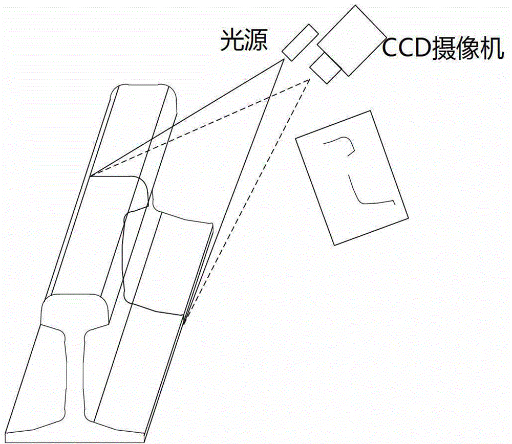
[0152] In this embodiment, the standard 60-track is used as the detection object. The camera adopts a CCD industrial camera with a German AVT-FC125 1934 interface, and the resolution is 1280×960 pixels. Image processing and data transfer capabilities. The laser outputs red planar structured light with a wavelength of 635nm and a power of 40mW. In the laboratory, the camera parameters and light plane equation parameters are calibrated first, and the spatial geometric relationship between the camera and the light plane is determined. Take pictures of the profile of 60 standard rail sections, such as Figure 6 As shown, its space curve is obtained after three-dimensional reconstruction, and the theoretical contour space coordinate value of the corresponding position is calculated through the acquisition of feature points. Table 1 lists the measured values ​​of the rail head contour parameters and the dynamically generated template theoretical values. From the perspective of err...


PUM


Abstract

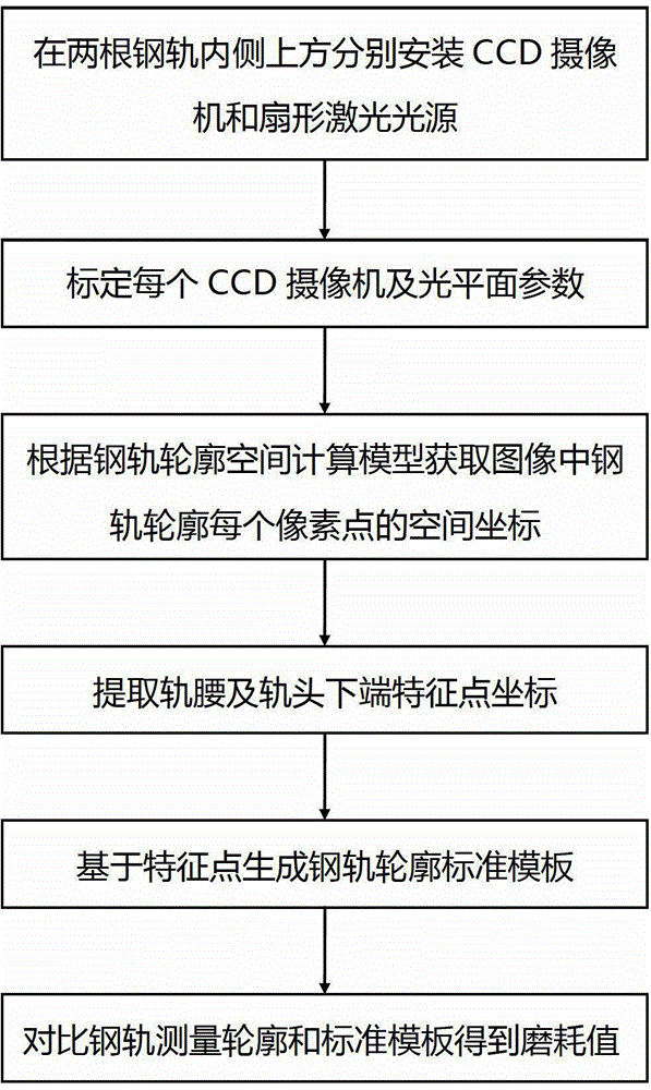
The invention provides a steel rail abrasion measuring method based on a dynamic template. The method comprises the steps of installing a charge coupled device (CCD) camera and a fan-shaped laser light source above the inside of two rails respectively; demarcating each CCD camera and an optical plane parameters; obtaining space coordinates of each pixel point of rail outlines in an image according to a rail outline space computation model; extracting feature point coordinates at the lower end of a rail waist and a rail head; generating a rail outline standard template based on feature points; and contrasting a rail measurement outline to the standard template to obtain abrasion value. The method can build a measurement coordinate system by determining two feature points of a measurement rail according to geometrical relationship of a standard rail outline, can fast and accurately obtain the standard template, does not need conduct aligning analysis of the measurement outline and a standard design outline, solves the problem that method based on a static template is difficult to match, greatly improves accuracy of abrasion measurement, reduces operation quantity of image analysis and processing and has good stability.

Description

technical field [0001] The invention relates to rail transit technology, in particular to a method for measuring rail wear based on a dynamic template. Background technique [0002] The wear and tear of the rail generally mainly occurs at the rail head, which is the main factor determining the service life of the rail. On the one hand, the abrasion accelerates the wear of the locomotive wheels, increases the gauge, and increases the contact area with the locomotive wheel tread, which increases the running resistance; on the other hand, it produces serious noise. When the wear exceeds a certain limit, the rail head section and the wheel tread will lose their matching, which will seriously affect the running stability of the high-speed railway and cause great harm to the driving safety. Especially for high-speed railways, when the speed of the train is high, even small wear and tear can cause the train to derail. [0003] At present, the most researched in wear detection in ...

Claims


Application Information

Patent Timeline
Patent Type & Authority Patents(China)
IPC IPC(8): G01B21/20B61K9/08
Inventor 郑树彬柴晓冬安小雪李立明许晓伟刘新厂蒋啟榛
Owner SHANGHAI UNIV OF ENG SCI
Learn More