
Shell-and-tube heat exchanger

A technology of shell-and-tube heat exchangers and heat exchange tubes, which is applied in the direction of heat exchanger types, heat exchanger shells, indirect heat exchangers, etc., and can solve problems such as unfavorable industrial standardization, high processing costs, and difficulty in ensuring product accuracy.

Inactive Publication Date: 2012-10-24
CHINA PETROLEUM & CHEM CORP
View PDF5 Cites 8 Cited by
  • Summary
  • Abstract
  • Description
  • Claims
  • Application Information

AI Technical Summary

Problems solved by technology

Although this type of spiral baffle makes the flow form of the shell side fluid more reasonable, increases the effective flow area, and reduces the flow resistance, but compared with the bow-shaped baffle, the spiral baffle is difficult to install, the processing cost is high, and the product accuracy is difficult. Guaranteed, detrimental to industry standardization

Method used


Image

  • Shell-and-tube heat exchanger
  • Shell-and-tube heat exchanger
  • Shell-and-tube heat exchanger

Examples


Embodiment Construction

[0026] Specific embodiments of the present invention will be described in detail below in conjunction with the accompanying drawings. It should be understood that the specific embodiments described here are only used to illustrate and explain the present invention, and are not intended to limit the present invention.

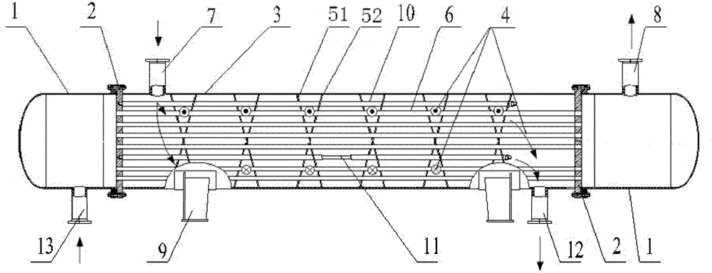
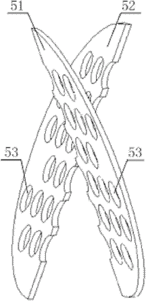
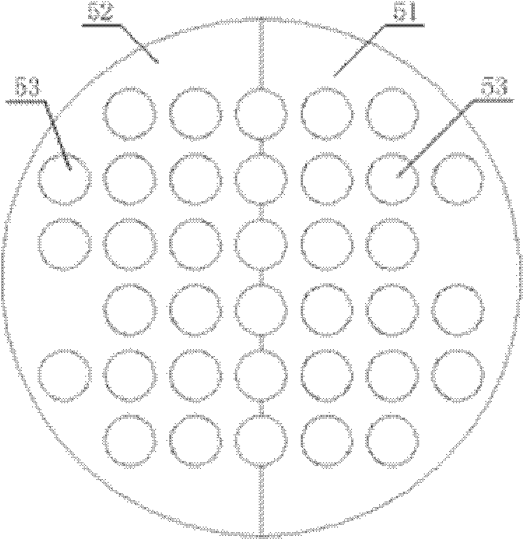
[0027] Such as Figure 1 to Figure 4 As shown, a shell-and-tube heat exchanger is provided according to an embodiment of the present utility model, and the shell-and-tube heat exchanger includes a shell 3 and a plurality of heat exchange tubes 6 arranged in the shell 3 and A plurality of baffles, the heat exchange tube 6 passes through each baffle, and the plurality of baffles are arranged at intervals along the axial direction of the heat exchange tube 6, wherein each of the baffles includes a first plate 51 and a second plate 51 Two boards 52, the board surfaces of the first board 51 and the second board 52 cross each other.

[0028] Through the above techni...


PUM


Abstract

The invention discloses a shell-and-tube heat exchanger which comprises a casing (3), a plurality of heat exchange tubes (6) and a plurality of whirl plates, wherein the heat exchange tubes and the whirl plates are arranged in the casing (3), the heat exchange tubes (6) pass through each whirl plate, and the plurality of whirl plates are arranged at intervals along the axial direction of the heat exchange tubes (6). Each whirl plate comprises a first plate (51) and a second plate (52), and plate faces of the first plate (51) and the second plate (52) are mutually crossed. By means of the technical scheme, shell side fluid can sequentially pass through a staggered area of each whirl plate to spirally and continuously flow, shell side fluid flow modes are reasonable, effective flow area is expanded, flow resistance is reduced, and vibration and abrasion of the heat exchange tubes are slowed down. In addition, an installation mode same with that of a common arch whirl plate can be adopted for installation, so that the shell-and-tube heat exchanger is easy to install, low in manufacture cost, capable of guaranteeing product accuracy and favorable for industrial standardization.

Description

technical field [0001] The present invention relates to a heat exchanger, more particularly, to a shell-and-tube heat exchanger. Background technique [0002] Shell and tube heat exchangers are widely used in petrochemical, electric power, environmental protection and other industrial fields. Shell and tube heat exchangers usually include tube boxes, tube sheets, shells, multiple baffles, multiple heat exchange tubes, tie rods and spacer tubes, etc. Among them, in addition to supporting the heat exchange tubes in the shell of the shell-and-tube heat exchanger, the baffle mainly plays the role of making the fluid flow according to a specific path, increasing the flow rate of the shell-side fluid, increasing the degree of turbulence, and improving the heat transfer characteristics. . The baffles of the existing shell-and-tube heat exchangers include arcuate baffles and spiral baffles. Ordinary arcuate baffles are flat plates, that is, generally circular flat plates are cut ...

Claims


Application Information

Patent Timeline
IPC IPC(8): F28D7/16F28F9/24
Inventor 钱才富龚宏戴凌汉孙海阳徐鸿范德顺
Owner CHINA PETROLEUM & CHEM CORP
Learn More