
Eccentric gear turning rotary platform

A gear turning and turning table technology, applied in turning equipment, tool holder accessories, metal processing equipment, etc., can solve the problems of inability to move greatly, hidden dangers, repairs, etc., and improve work efficiency and safety factor. High, easy to debug effect

Inactive Publication Date: 2012-10-24
JIANGSU XUZHOU METALFORMING MACHINE GROUP
View PDF4 Cites 0 Cited by
  • Summary
  • Abstract
  • Description
  • Claims
  • Application Information

AI Technical Summary

Problems solved by technology

[0002] At present, the machining of the eccentric gear and eccentric cylinder of the domestic closed single-double point press is mainly carried out on a vertical lathe, and the adjustment of its eccentricity and precision mainly depends on the operator to carry out careful clamping and repeated Correction is guaranteed, and in the process of processing, there is no counterweight structure to balance the centrifugal force brought by the eccentric body part of the workpiece during the rotation process, and there is a large safety hazard during the rotation process
For workpieces with larger shapes and heavier weights, each clamping and calibration must be lifted by a crane, and it must be ensured that large movements cannot be made during lifting. Once it touches other objects during the movement, the clamping will be lost. It takes a lot of time and energy to re-calibrate the accuracy of the card. Not only is the efficiency low, but the accuracy of the eccentricity cannot be effectively guaranteed, which often causes the workpiece to be unqualified and needs to be repaired or even scrapped, which costs a lot of workpieces. The clamping time is long, and it is not easy to meet the size requirements of the workpiece

Method used


Image

  • Eccentric gear turning rotary platform
  • Eccentric gear turning rotary platform
  • Eccentric gear turning rotary platform

Examples


Embodiment Construction

[0013] The present invention will be further described below in conjunction with accompanying drawing.

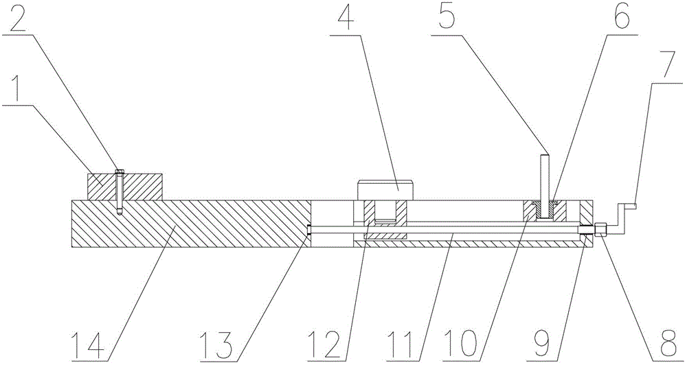
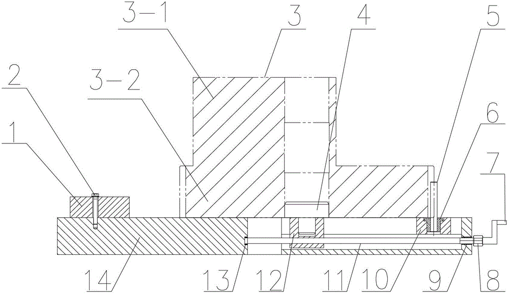
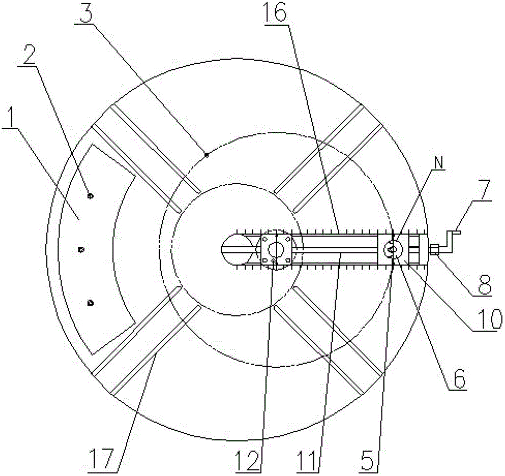
[0014] Such as figure 1 As shown, the eccentric gear turning table includes a circular chassis 14, a U-shaped groove guide rail is arranged in the radial direction of the circular chassis 14, and a center indicator line is marked on the circular chassis 14, and a lead screw 11 is worn in the middle of the U-shaped groove guide rail. , the inner end and the outer end of the screw 11 are respectively supported in the U-shaped groove guide rail by the bearing 13 and the copper sleeve 9, and a threaded pointer slider 12 is worn on the screw 11, and the pointer slider 12 is engraved with a pointer, A mandrel 4 is inlaid in the pointer slider 12, the handle 7 is connected with the lead screw 11 through a nut 8, and a floating slider 10 is also arranged in the U-shaped groove guide rail of the round chassis 14, and the floating slider 10 is inlaid with a There is a positioning sl...


PUM


Abstract

The invention discloses an eccentric gear turning rotary platform and belongs to the technical field of turning devices. The eccentric gear turning rotary platform comprises a round chassis. A U-shaped groove guide rail is arranged on the round chassis in the radial direction, a lead screw penetrates through the middle of the U-shaped groove guide rail, and the inner end and the outer end of the lead screw are respectively supported by bearings and copper sleeves in the U-shaped groove guide rail. A pointer slide block with threads penetrates into the upper portion of the lead screw, a mandrel is inlayed into the pointer slide block, and a handle is connected with the lead screw through a nut. A moving slide block is further arranged in the U-shaped groove guide rail of the round chassis, a positioning sleeve is inlayed in the moving slide block, and a positioning rod penetrates into an inner hole of the positioning sleeve. The eccentricity of the turning rotary platform can be accurately adjusted, debugging is convenient, the precision is high, and the work efficiency is improved greatly. After counter weight iron is installed, security coefficient is high when an eccentric cylinder of an eccentric gear is processed.

Description

technical field [0001] The invention relates to an eccentric gear turning turntable, which belongs to the technical field of turning devices. Background technique [0002] At present, the processing of the eccentric gear eccentric cylinder of the domestic closed single-double point press is mainly carried out on a vertical lathe, and the adjustment of its eccentricity and precision mainly depends on the operator to carry out careful clamping and repeated Calibration is guaranteed, and in the process of processing, there is no counterweight structure to balance the centrifugal force brought by the eccentric body part of the workpiece during the rotation process, and there is a large safety hazard during the rotation process. For workpieces with larger shapes and heavier weights, every clamping and calibration must be lifted by a crane, and it must be ensured that large movements cannot be made during lifting. Once touching other objects during the moving process, the clamping...

Claims


Application Information

Patent Timeline
Patent Type & Authority Applications(China)
IPC IPC(8): B23B25/06
Inventor 张远秦剑柯尊芒梁化春厉慧
Owner JIANGSU XUZHOU METALFORMING MACHINE GROUP
Learn More