Electric power conversion device

A power conversion device and current technology, applied in circuit devices, output power conversion devices, electrical components, etc., can solve problems such as IGBT damage

Inactive Publication Date: 2012-10-17
HITACHI LTD
View PDF4 Cites 2 Cited by
  • Summary
  • Abstract
  • Description
  • Claims
  • Application Information

AI Technical Summary

Problems solved by technology

[0013] When the inductance of the single-phase reactor is zero, the harmonic current (hereinafter referred to as "circulating harmonic current") circulating in the three clusters due to the zero-phase harmonic voltage is excessive. large, thus becoming the cause of destruction of the IGBTs within the cluster

Method used


Image

  • Electric power conversion device
  • Electric power conversion device
  • Electric power conversion device

Examples


Embodiment 1

[0049] A first embodiment of the present invention will be described.

[0050] In Embodiment 1, a delta connection CMC is realized that significantly reduces the volume and weight of a reactor (reactor) as compared with the conventional delta connection CMC.

[0051] Below, use figure 1 The overall structure of Example 1 will be described.

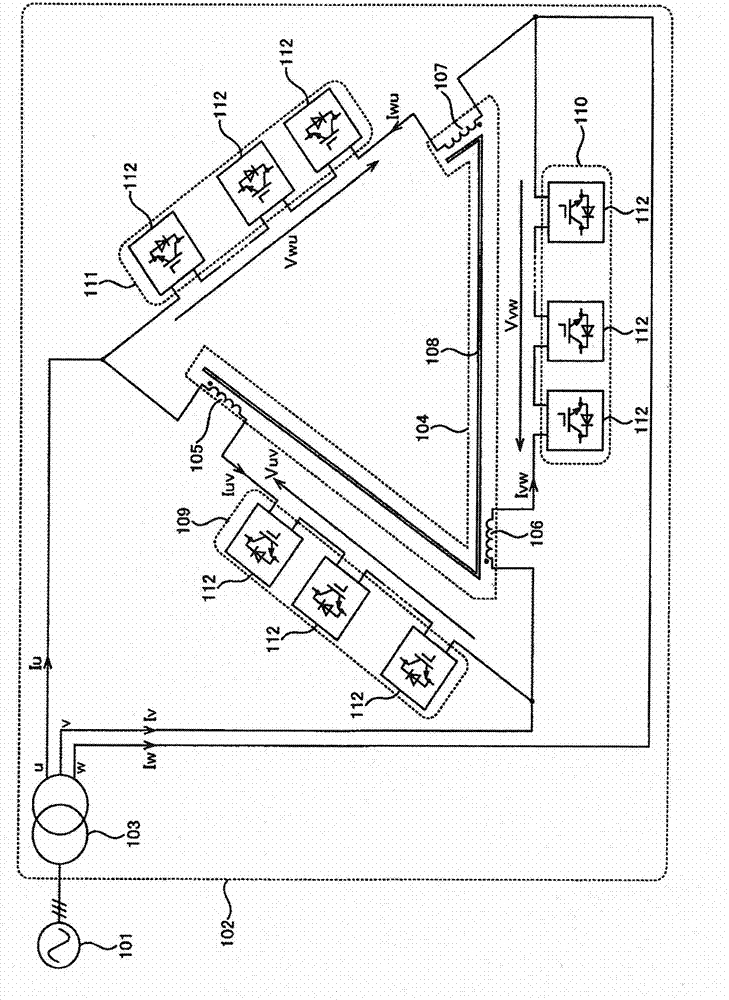
[0052] The power conversion device 102 interconnected with the power system 101 is composed of a transformer 103 , a common core reactor 104 , a uv-phase cluster 109 , a vw-phase cluster 110 , and a wu-phase cluster 111 .

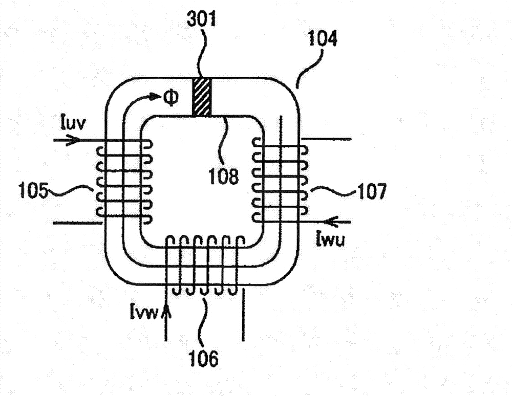
[0053] The common core reactor 104 is composed of uv-phase windings 105, vw-phase windings 106, wu-phase windings 107, and a common iron core 108. The uv, vw, and wu-phase windings 105-107 are polarized with magnetomotive force Wound on the common core 108.

[0054] The uv phase cluster 109 and the uv phase winding 105 are connected in series. Likewise, the vw-phase cluster 110 and the vw-phase winding 106 , and the...

Embodiment 2

[0133] Next, a second embodiment of the present invention will be described.

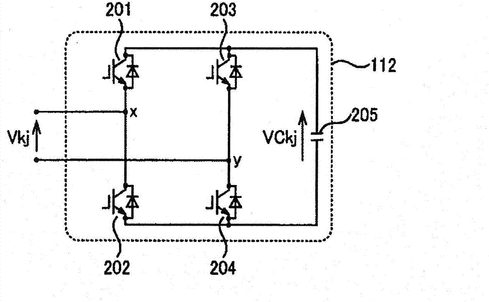
[0134] In Embodiment 2, instead of the unit cell 112 of Embodiment 1 figure 2 ,use Figure 7 A unit cell 701 is shown with an active power supply mechanism 702 connected.

[0135] Thus, in the second embodiment, effective electric power can be received between the power system 101 and the power conversion device 102 .

[0136] Hereinafter, the overall structure of Embodiment 2 will be described.

[0137] In Example 2, in figure 1 In the power conversion device 102 shown, the M unit cells 112 included in each of the clusters 109 to 111 are configured to be figure 2 The unit cell shown is replaced by Figure 7 A unit cell 701 is shown with an active power supply mechanism 702 connected thereto.

[0138] In addition, the whole structure is the same as that of Example 1 except for this point.

[0139] Below, refer to Figure 5 Control when the power conversion device 102 receives active power ...


PUM


Abstract

Provided is an electric power conversion device which eliminates the need for large-capacity heavy single-phase reactors of previous delta connection cascade multilevel converters (CMCs), where the delta connection CMCs are formed by delta connection of three single-phase converters. Disclosed is an electric power conversion device provided with a formation of three delta-connected strings of series-connected windings and clusters, where the clusters are comprised of one or a plurality of cascade-connected single cells, and a common iron core reactor is formed by the three windings coiled around a common iron core such that their magnetomotive force provides additive polarity.

Description

technical field [0001] The present invention relates to a power conversion device, in particular to a three-phase converter formed by delta-connecting three single-phase converters. Background technique [0002] A delta junction cascade multilevel converter (hereinafter referred to as "CMC") is capable of outputting the above-mentioned A circuit system with a voltage higher than the withstand voltage of the switching element. According to [Non-Patent Document 1], the delta-connection CMC is configured by delta-connecting three clusters, which are series bodies of a plurality of unit cells, and series bodies of single-phase reactors. [0003] According to [Non-Patent Document 1], each unit cell is a single-phase full-bridge circuit including a switching element and a DC capacitor. The unit cell outputs a DC capacitor voltage, a voltage of the reverse polarity of the DC capacitor voltage, or zero voltage by controlling ON / OFF of the switching element. [0004] Since each cl...

Claims


Application Information

Patent Timeline
Patent Type & Authority Applications(China)
IPC IPC(8): H02M7/49
CPCH02J3/1857H02M7/49Y02E40/26H02M2007/4835Y02E40/20H02M1/0064H02M7/4835
Inventor 井上重德加藤修治
Owner HITACHI LTD
Why Eureka
Try Eureka