Service quality optimization method and system, network side network element
A technology of service quality and optimization method, applied in the field of network elements on the network side, can solve problems such as inappropriate matching and failure to meet user QoS requirements, and achieve the effect of increasing QoS quality and improving user experience
- Summary
- Abstract
- Description
- Claims
- Application Information
AI Technical Summary
Problems solved by technology
Method used
Image

Examples
Embodiment 1
[0066] This embodiment provides a QoS optimization method by taking the periodic measurement reporting on the terminal side as an example. It is assumed that the services measured in this embodiment are all uplink services, the terminal is in a link state in network element 1 (eg, eNB or RNC), and the cell of network element 1 provides services for the terminal.
[0067] Figure 4 It is a schematic flowchart of periodically reporting PDCP measurement results according to Embodiment 1 of the present invention, such as Figure 4 shown, the process includes the following steps:
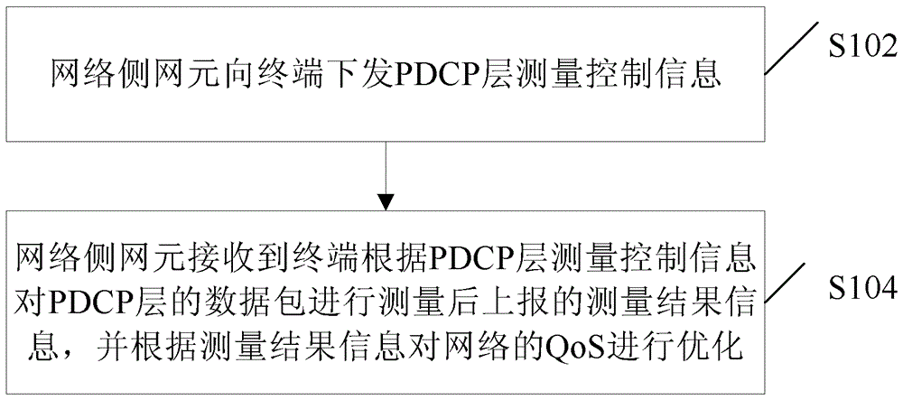
[0068] Step S402, based on QoS optimization or other requirements, the network element 1 delivers PDCP layer measurement control information to the terminal. Wherein, the measurement control information may include one or more of the target measurement amount of measurement, the target process of measurement, measurement reporting information, and the like. In the implementation process, the target me...
Embodiment 2
[0077] This embodiment provides an optimization solution for QoS by taking event-triggered measurement reporting as an example. It is assumed that the services measured in this embodiment are all uplink services, the terminal is in a link state in the network element 1, and the cell of the network element 1 provides services for the terminal.
[0078] Figure 5 It is a schematic flowchart of the event reporting PDCP measurement result according to Embodiment 2 of the present invention, as shown in Figure 5 shown, the process includes the following steps:
[0079] Step S502, based on QoS optimization or other requirements, the network element 1 delivers PDCP layer measurement control information to the terminal. Wherein, the measurement control information includes the target measurement amount of measurement, and may also include one or more of the target process of measurement, measurement reporting information, and the like. The target measurement amount includes the mea...
Embodiment 3
[0088] This embodiment provides a QoS optimization system scheme by taking the example that both the start of the measurement at the PDCP layer and the reporting of the measurement result are triggered by an event.
[0089] Image 6 It is a schematic flowchart of event-triggered measurement and event-triggered measurement result reporting according to Embodiment 3 of the present invention, such as Image 6 As shown, the terminal is in the link state in the network element 1, and the network element 1 provides services for the terminal. The process includes the following steps:
[0090]Step S602, based on QoS optimization or other requirements, the network element 1 delivers the PDCP layer measurement control information to the terminal. Wherein, the measurement control information includes the target measurement amount of measurement, and may also include one or more of the target process of measurement, measurement trigger information, measurement report information, and the...
PUM
 Abstract
Description
Claims
Application Information
 - R&D
- Intellectual Property
- Life Sciences
- Materials
- Tech Scout
- Unparalleled Data Quality
- Higher Quality Content
- 60% Fewer Hallucinations
Browse by: Latest US Patents, China's latest patents, Technical Efficacy Thesaurus, Application Domain, Technology Topic, Popular Technical Reports.
© 2025 PatSnap. All rights reserved.Legal|Privacy policy|Modern Slavery Act Transparency Statement|Sitemap|About US| Contact US: help@patsnap.com