Pressure reducing valve having shutoff mechanism

A technology of cut-off mechanism and pressure reducing valve, which is applied in the direction of fluid pressure control, safety valve, balance valve, etc., can solve the problems of complex internal structure, large-scale product and high cost, so as to suppress the increase of cost and realize miniaturization. , the effect of preventing deterioration

Inactive Publication Date: 2012-10-17
HONDA MOTOR CO LTD
View PDF8 Cites 5 Cited by
  • Summary
  • Abstract
  • Description
  • Claims
  • Application Information

AI Technical Summary

Problems solved by technology

[0008] However, in the above-mentioned conventional pressure reducing valve, since various valve mechanisms are incorporated in the pressure reducing valve unit, the internal structure becomes complicated, resulting in an increase in product size and cost.

Method used


Image

  • Pressure reducing valve having shutoff mechanism
  • Pressure reducing valve having shutoff mechanism
  • Pressure reducing valve having shutoff mechanism

Examples


Embodiment Construction

[0030] Hereinafter, an embodiment of the present invention will be described based on the drawings.

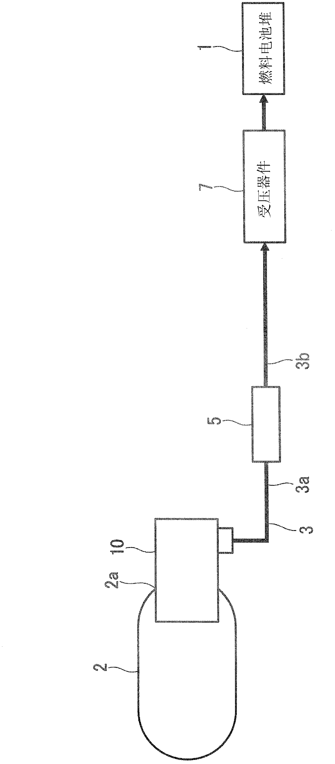
[0031] figure 1 It is a schematic configuration diagram of a fuel cell system, and reference numeral 1 denotes a fuel cell stack (fuel cell) that is supplied with hydrogen as a fuel and oxygen as an oxidant to generate electricity. The fuel cell stack 1 is, for example, a solid polymer fuel cell (Polymer Electrolyte Fuel Cell: PEFC), and is a single stack in which a MEA (Membrane Electrode Assembly, membrane electrode assembly) is sandwiched by separators (not shown). made of batteries.

[0032] Hydrogen gas at a predetermined pressure and a predetermined flow rate is supplied to the fuel cell stack 1 from a hydrogen storage tank 2 storing high-pressure hydrogen (a supply source of high-pressure fluid) through a hydrogen supply flow path 3, and at a predetermined pressure through an air supply device (not shown). Oxygen-containing air is supplied to the fuel cell stack 1 at ...


PUM


Abstract

A high-pressure side primary pressure chamber communicates with a secondary pressure chamber on the side of a pressure receiving device through a communication hole. A diaphragm which receives the pressure in the secondary pressure chamber is provided, and a valve body is connected to the diaphragm. The diaphragm is biased by a spring in a valve opening direction. The area S (mm2) of the pressure receiving surface of the diaphragm and the spring constant k (N / mm) of the spring are set so as to satisfy the following equations (1) and (2). P1S-k[Delta]L>C (1) P1<P2 (2) where P1 denotes the pressure (MPa or N / mm2) of the secondary pressure chamber, [Delta]L denotes the displacement (mm) of the spring, C denotes the minimum closing load (N) of the valve body, and P2 denotes the allowable maximum pressure (MPa or N / mm2) of the pressure receiving device.

Description

technical field [0001] The present invention relates to a pressure reducing valve that depressurizes high-pressure fluid on the supply source side to a predetermined pressure and supplies it to a low-pressure passage where a pressure receiving device exists. A pressure reducing valve with a shut-off mechanism capable of side leakage of high-pressure fluid. Background technique [0002] In a fuel cell, a hydrogen storage tank filled with high-pressure hydrogen is sometimes used as a fluid supply source on the anode side. In systems dealing with such high-pressure fluids, a pressure reducing valve is installed between the supply source of the high-pressure fluid and the pressure-receiving device, and the high-pressure fluid from the fluid supply source is decompressed to a predetermined pressure by the pressure-reducing valve and then supplied to the pressure-receiving device. [0003] As a pressure reducing valve used in such an application, there is known a structure in whi...

Claims


Application Information

Patent Timeline
Patent Type & Authority Applications(China)
IPC IPC(8): F16K17/04
CPCG05D16/0655G05D16/0658Y10T137/782
Inventor 三浦种昭尾崎浩靖高久晃一加藤航一
Owner HONDA MOTOR CO LTD
Why Eureka
Try Eureka