
Construction method and device for advance support of front probing beam

A technology of advanced support and forward detection beam, which is applied in the direction of supporting the top beam of the mine roof, earthwork drilling and mining, mining equipment, etc. In order to solve problems such as lack of supporting effect, it can achieve the effect of convenient structure acquisition and forward movement, small workload, and enhanced overall supporting effect

Inactive Publication Date: 2014-10-22
SHANDONG UNIV OF SCI & TECH +1
View PDF5 Cites 0 Cited by
  • Summary
  • Abstract
  • Description
  • Claims
  • Application Information

AI Technical Summary

Problems solved by technology

One is that the front beam cannot directly drag the roof, and to a certain extent it cannot play a supporting role. It can only buffer the collapse and cannot provide essential protection for the workers under the front beam; During the downhill excavation, the front beam slipped and easily injured people

Method used


Image

  • Construction method and device for advance support of front probing beam
  • Construction method and device for advance support of front probing beam

Examples


Embodiment Construction

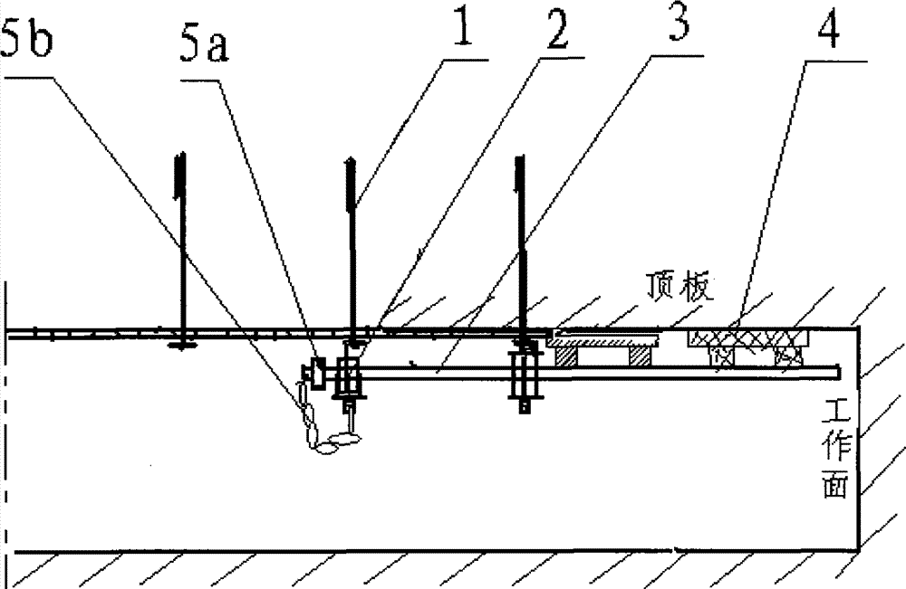
[0019] Such as figure 1 As shown, a kind of advance support construction method of the front probe beam, it is to reserve 30cm-50cm length for the exposed end of the thread of the anchor rod 1 at the top of the roadway when the roadway anchor net is sprayed for a support, so that the thread of the anchor rod 1 The head is exposed to the support surface, and then through the threaded head of the anchor rod 1, install the front and rear two height-adjustable suspension rings 2, insert the front probe beam 3 into the two suspension rings 2, and extend forward to the working On the surface, put a skid 4 in the gap between the front beam 3 and the top plate, adjust the height of the two suspension rings 2, thereby adjusting the angle at which the front beam 3 protrudes, and make the front end of the front beam 3 support the suspended roof; In order to prevent the front beam from slipping, the rear end of the front beam should be provided with a stopper 5a and a hanging chain 5b. I...


PUM


Abstract

The invention discloses forepoling bar forpoling construction method and a device used. The method comprises the steps of: reserving 30-50cm length of a thread exposed end of an anchor rod at the top of a laneway during one-time spraying poling of the anchored net for the laneway, enabling the thread head of the anchor rod to be exposed out of the surface of the polling, installing front and rear suspension rings with adjustable heights through the thread head of the anchor rod, inserting forepoling bars into the two suspension rings, forward extending to a working surface, cushioning a sole timber in a clearance between the forepoling bar and a top plate, and adjusting the heights of the two suspension rings, thus adjusting the extending angle of the forepoling bar and enabling the front end of the forepoling bar to support the suspended top plate. The construction method enables the forepoling bar to move forward to the greatest extent, and maximizes the construction operation space of the anchored net, thus facilitating construction for workers; and the forepoling part of the forepoling bar is clung to the top plate, thus enhancing the whole supporting action of the forepoling bar, and being capable of effectively supporting the top plate even under the condition small inbreak or underbreak of the top plate.

Description

technical field [0001] The invention relates to a temporary support during roadway excavation. Background technique [0002] At present, anchor mesh spraying has become the development trend of roadway support technology. It has the advantages of low support cost, good support effect and high single-feed speed. In the process of the development of the bolt-net-spray support technology, the corresponding supporting temporary support is also constantly updated, such as wooden top columns, capped point columns, and advanced support of the front probe beam. Especially when passing through faults and soft rock fracture zones, the advance support of the front beam has certain advantages. The technology related to this application is the advance support technology of the probing beam. [0003] In the practice of roadway excavation and support, it is found that there are still two disadvantages in the advance support technology of the front beam. One is that the front probe beam...

Claims


Application Information

Patent Timeline
Patent Type & Authority Patents(China)
IPC IPC(8): E21D17/00
Inventor 王渭明张德泉王永吉蒋守来王云博
Owner SHANDONG UNIV OF SCI & TECH
Learn More