Base used for fixedly installing light pole, telegraph pole and high-tension wire tower and installation method thereof
An installation method and a technology for utility poles, which are applied in the field of line pole frame fixing, can solve problems such as low efficiency, environmental pollution, waste of resources, etc., and achieve the effects of increased installation speed, low cost, and resource saving
- Summary
- Abstract
- Description
- Claims
- Application Information
AI Technical Summary
Problems solved by technology
Method used
Image
Examples
Embodiment 1
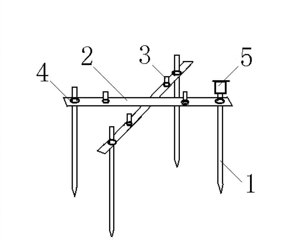
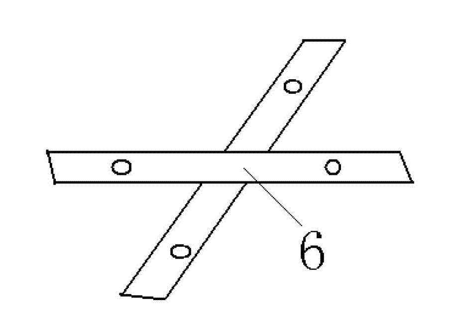
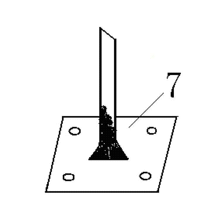
[0037] Example 1, such as Figure 1 to Figure 3 As shown, the geology of the installation position of the street light pole is soil, and the preferred technical solution for the base is: the base steel plate is two cross-shaped steel plates 2, the post is a reinforced post 1, and the bottom of the reinforced post 1 is pointed head, the top is provided with threads, the two ends of the bar-shaped steel plate 2 are fixedly connected with the top of the steel bar pile 1 through the nut 4, and there are threaded installation and fixing holes between the end of the bar-shaped steel plate and the intersection of the bar-shaped steel plate 15. The fixing hole 15 is threadedly connected with the fixing bolt 3 . The positions of the fixing bolts 3 on the strip steel plate 2 correspond to the positions of the mounting holes at the bottom 7 of the street light pole.
[0038] When the base is installed, set the criss-cross installation and reinforcement steel plates 6 on the fixing bolts...
Embodiment 2
[0042] Example 2, such as Figure 4 and Figure 5 As shown, the geology of the installation position of the utility pole is soil, and the preferred technical scheme of the base is: the base steel plate is three intersecting strip steel plates 2, the column piles are six steel pipe column piles 10, and the upper end of the steel pipe column pile is connected with the strip steel plate two The ends are fixedly connected by nuts 4, and the bottom of the steel pipe column pile 10 is provided with a pointed screw 9, which is convenient for pressing into the ground.
[0043] Preferably, a circular reinforcing steel plate 8 is arranged above the strip steel plate 2, and the threaded holes on the reinforcing steel plate 8 are connected with the fixing bolts 3 on the strip steel plate 2 to improve the strength of the base steel plate. The six steel pipe columns are on the same circle, and the connecting line is a regular hexagon to ensure the balance of the force on the base.
[0044...
Embodiment 3
[0047] Example 3, such as Figure 6 and Figure 7 As shown, the geology of the installation location of the high-voltage electric tower is rocky, and the preferred technical solution for the base is: the steel plate of the base is a whole steel plate, the column pile is an expansion bolt column pile 11, and the upper end of the expansion bolt column pile 11 is connected to the edge of the whole steel plate Connected by nuts 4, the threaded mounting and fixing holes 15 in the middle of the whole steel plate are connected with fixing bolts.
[0048] High-voltage power towers generally consist of four or six or even eight bases, which are most suitable for installing high-voltage power tower base groups on rocky mountains, and it is not necessary to make the stone surface into a horizontal plane, as long as Just increase the height of the downhill expansion bolt pile to ensure that the base steel plates are in a horizontal state, and at the same time ensure that the surfaces of ...
PUM
| Property | Measurement | Unit |
|---|---|---|
| Length | aaaaa | aaaaa |
Abstract
Description
Claims
Application Information
 - R&D Engineer
- R&D Manager
- IP Professional
- Industry Leading Data Capabilities
- Powerful AI technology
- Patent DNA Extraction
Browse by: Latest US Patents, China's latest patents, Technical Efficacy Thesaurus, Application Domain, Technology Topic, Popular Technical Reports.
© 2024 PatSnap. All rights reserved.Legal|Privacy policy|Modern Slavery Act Transparency Statement|Sitemap|About US| Contact US: help@patsnap.com


