
Chain tube mill

A technology of a pipe rolling mill and a chain pipe, which is applied in the field of chain pipe rolling mills, can solve problems such as unseen chain pipes, and achieve the effects of reducing flow resistance, changing heat exchange area, and enhancing heat exchange effect.

Inactive Publication Date: 2012-10-17
LIAONING TONGLIDA TECH
View PDF7 Cites 5 Cited by
  • Summary
  • Abstract
  • Description
  • Claims
  • Application Information

AI Technical Summary

Problems solved by technology

However, there is no report about the chain pipe and the forming equipment for manufacturing the chain pipe.

Method used


Image

  • Chain tube mill
  • Chain tube mill

Examples


Embodiment Construction

[0011] The present invention will be further described below in conjunction with the embodiments of the accompanying drawings.

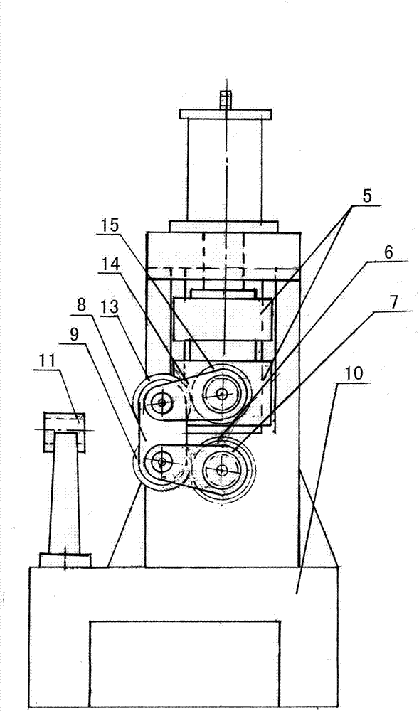
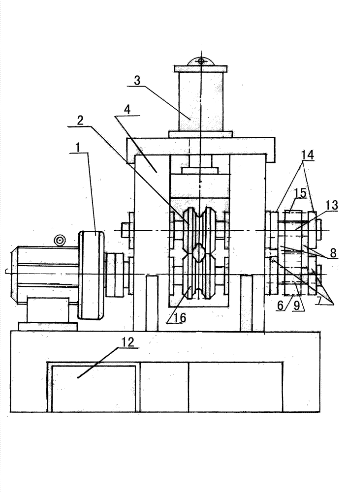
[0012] See figure 1 , figure 2 A chain pipe rolling mill shown includes a base 10, and a frame 4 installed on the base 10, a pair of active forming rollers 16 and passive forming rollers 2 are installed on the frame 4, the active One end of the forming roller 16 and the passive forming roller 2 leading out of the frame 4 is provided with a transmission mechanism, wherein the other end of the active forming roller 16 is connected with the reduction motor 1 . The passive forming roller 2 is connected with the hydraulic cylinder 3 located on the upper part of the frame 4 to control the lifting of the passive forming roller 2 through the slide block 5 symmetrically installed on the chute of the frame 4 , and the hydraulic cylinder 3 is connected with the pumping station 12 . The driving forming roller 16 and the passive forming roller 2 are driven by ...


PUM


Abstract

The invention discloses a chain tube mill, which comprises a base and a frame arranged on the base, wherein a driving forming roll and a driven forming roll are arranged on the frame as a pair; a leading-out terminal of one side of the driving forming roll and a leading-out terminal of one side of the driven forming roll are connected with the transmission mechanism; the other side end of the driving forming roll is connected with a speed-down motor; and the driven forming roll is connected with a hydraulic oil cylinder positioned on the upper frame through sliding blocks symmetrically arranged on the frame chute. The chain tube can reduce flow resistance, change heat exchange area, change fluid flushing force in the tube and enhance heat exchange effect, and scaling is avoided. A chain tube continuously formed by using the chain tube mill fills the blank in the field.

Description

technical field [0001] The invention relates to a pipe rolling machine, in particular to a chain pipe rolling machine. Background technique [0002] The heat exchange tubes currently used in heat exchangers include straight tubes, corrugated tubes and spiral tubes. Since corrugated tubes and spiral tubes have better heat transfer effects, they replace the application of straight tubes. Therefore, there are special equipment for the manufacture of corrugated tubes and spiral tubes. However, because of the relatively high manufacturing costs of the corrugated tubes and spiral tubes, the overall cost of the heat exchanger is increased. After research, it was found that the chain pipe can also reduce the flow resistance, is not easy to generate scaling, and can enhance the heat exchange effect. But do not see relevant chain pipe at present, and the report of the forming equipment of manufacturing chain pipe. Contents of the invention [0003] The object of the present inve...

Claims


Application Information

Patent Timeline
Patent Type & Authority Applications(China)
IPC IPC(8): B21D15/06
Inventor 孙清堂罗军杰王延龙刘杰
Owner LIAONING TONGLIDA TECH
Learn More